Image evaluation apparatus and method

a technology of image evaluation and apparatus, applied in the direction of image enhancement, visual presentation using printers, instruments, etc., can solve the problems of measurement being impossible, accuracy degraded, and other defects than the deviation of the dot position being measured in the image evaluation

Inactive Publication Date: 2008-03-11
RICOH KK
View PDF8 Cites 1 Cited by
  • Summary
  • Abstract
  • Description
  • Claims
  • Application Information

AI Technical Summary

Benefits of technology

[0034]According to this arrangement, the influences from unevenness in the density of the read out image caused by an inconsistency in the distribution of the irradiation light irradiated from the image input apparatus upon inputting the image to the input apparatus can be eliminated. As for the correction method, the read out image signals of the reproduced image may be subtracted from the base image, for example.
[0035]The signal levels of the image signals obtained from reading a consistent image with a fixed density (base image signal), and image signals of the support medium (paper) portion surrounding the dot of the reproduced image are su

Problems solved by technology

As a result, the accuracy in the image evaluation may be degraded, and in some cases, measurement may be impossible.
However, it is known that defects other than the dot position deviation being measured in the image evaluation also exist, such as the deviation in the image magnification due to the expansion or contraction of the support medium (paper) of the reproduced image, or a skew gen

Method used


Image

  • Image evaluation apparatus and method
  • Image evaluation apparatus and method
  • Image evaluation apparatus and method

Examples


Embodiment Construction

[0061]In the following, preferred embodiments of the present invention are described with reference to the accompanying drawings.

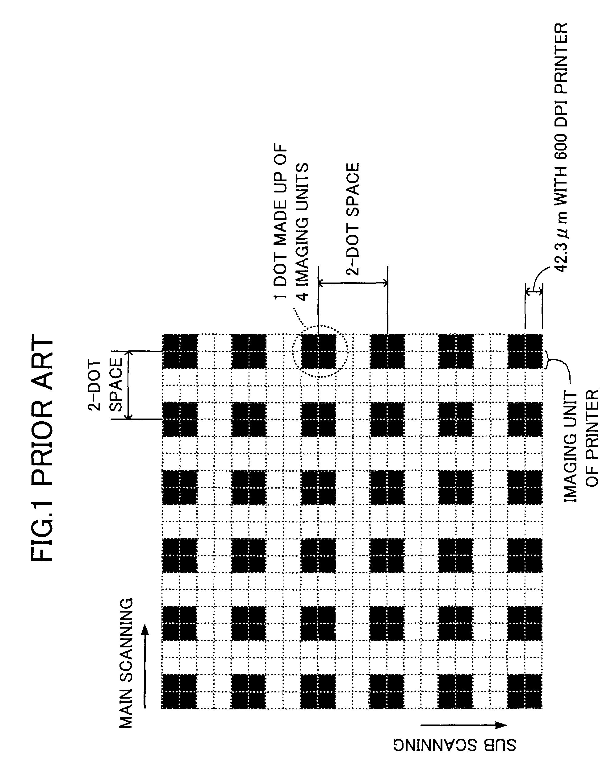
[0062]FIG. 3 shows a print pattern used in an embodiment of the present invention. This print pattern is made up of dots arranged in the main scanning direction and the sub scanning direction at dot pitches that are 2.5 times the designated dot dimension in the imaging apparatus being evaluated.

[0063]One dot is formed by 2×2 imaging units of the imaging apparatus. In this case, if the resolution of the imaging apparatus is 600 dpi, the dimension of one dot in the print pattern will be 84.6 μm. The dots are arranged to have a 2×2 configuration so that stability can be sufficiently maintained; that is, when the dots have a 1×1 configuration, the imaged dots are often unstable. It is noted that a stable dot configuration refers to a state in which each dot stands alone independently without sticking to adjacent dots.

[0064]The dot pitch is arranged to be 2.5 t...


PUM


Abstract

An image evaluation program is implemented in an image evaluation apparatus to evaluate a dot of an image that is reproduced on a support medium by an imaging apparatus and formed by a plurality of dots having a predetermined dimension arranged in a main scanning direction and a sub scanning direction. The image evaluation apparatus produces image signals at a resolution at least twice as high as a dot resolution of the image, and the image evaluation program is arranged to measure a dot position of each dot in the image.

Description

BACKGROUND OF THE INVENTION[0001]1. Field of the Invention[0002]The present invention relates generally to an apparatus and method for accurately measuring and examining dot position deviation and dot density fluctuation in a sub scanning direction of a printed image in order to evaluate printer performance. Particularly, the present invention relates to a technique for detecting cyclic fluctuation of a variation in dot position and cyclic fluctuation of a variation in dot size generated in a sub scanning operation performed by an imaging apparatus such as an electrophotographic printer that forms a two-dimensional image by generating a one-dimensional dot line extending in a horizontal (main scanning) direction and successively repeating the dot line formation in a vertical (sub scanning) direction.[0003]2. Description of the Related Art[0004]Prior art publications relating to the present invention are disclosed in Japanese Patent Laid-Open Publication No.7-175933 (“Image Evaluatio...

Claims


Application Information

Patent Timeline
IPC IPC(8): G06K15/02G06F15/00B41J29/46G03G21/00G06T7/60H04N1/00
CPCH04N1/00002H04N1/00015H04N1/00031H04N1/00047H04N1/00053H04N1/00061H04N1/00068
Inventor NAKASHIGE, FUMIHIRONOMOTO, MITSUMASA
Owner RICOH KK
Why Eureka
Try Eureka