Wireless communication method, wireless communication apparatus, and wireless communication system

a wireless communication and wireless communication technology, applied in wireless communication, wireless communication, broadcast service distribution, etc., can solve the problems of complicated control in the base station, insufficient overall data transmission efficiency of the system, and limited wireless communication to be performed in all frequency channels. , to achieve the effect of improving channel utilization efficiency and increasing the bandwidth of a frequency channel

Inactive Publication Date: 2008-03-11
KK TOSHIBA
View PDF12 Cites 12 Cited by
  • Summary
  • Abstract
  • Description
  • Claims
  • Application Information

AI Technical Summary

Benefits of technology

[0007]It is an object of the present invention to improve the channel utilization efficiency in a period in which a legacy wireless terminal can communicate in a wireless communication system wherein, a terminal which can increase the bandwidth of a frequency channel and perform high-throughput wireless communication coexists with the legacy wireless terminal which cannot perform such high-throughput wireless communication.

Problems solved by technology

In addition, wireless communication to be performed in all frequency channels is limited to that between the base station and the mobile stations.
When the base station is to serve as an entity to control frame exchange in all frequency channels, the control in the base station obviously becomes complicated.
In this case, the overall data transmission efficiency of the system is not necessarily good.

Method used


Image

  • Wireless communication method, wireless communication apparatus, and wireless communication system
  • Wireless communication method, wireless communication apparatus, and wireless communication system
  • Wireless communication method, wireless communication apparatus, and wireless communication system

Examples


first embodiment

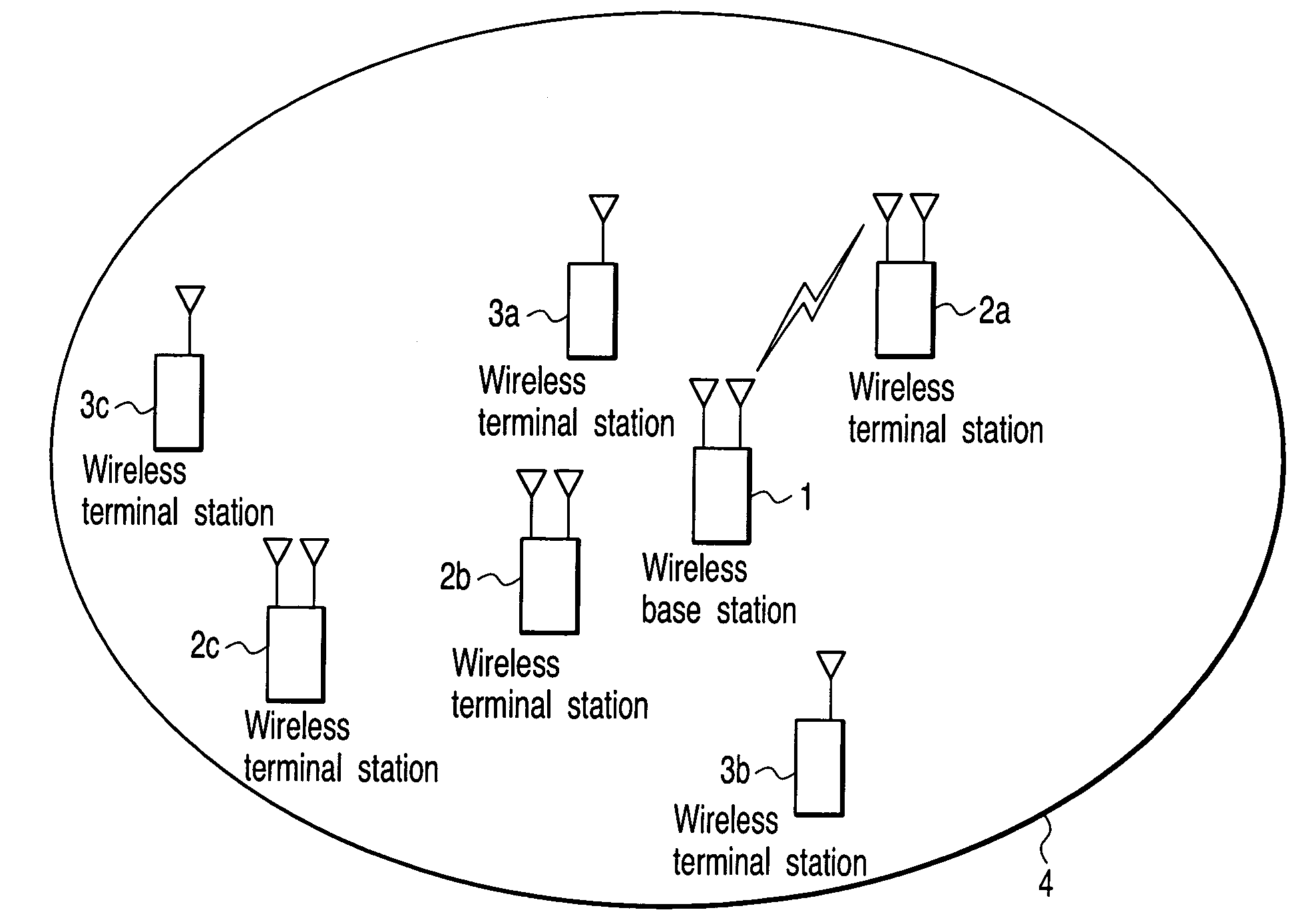
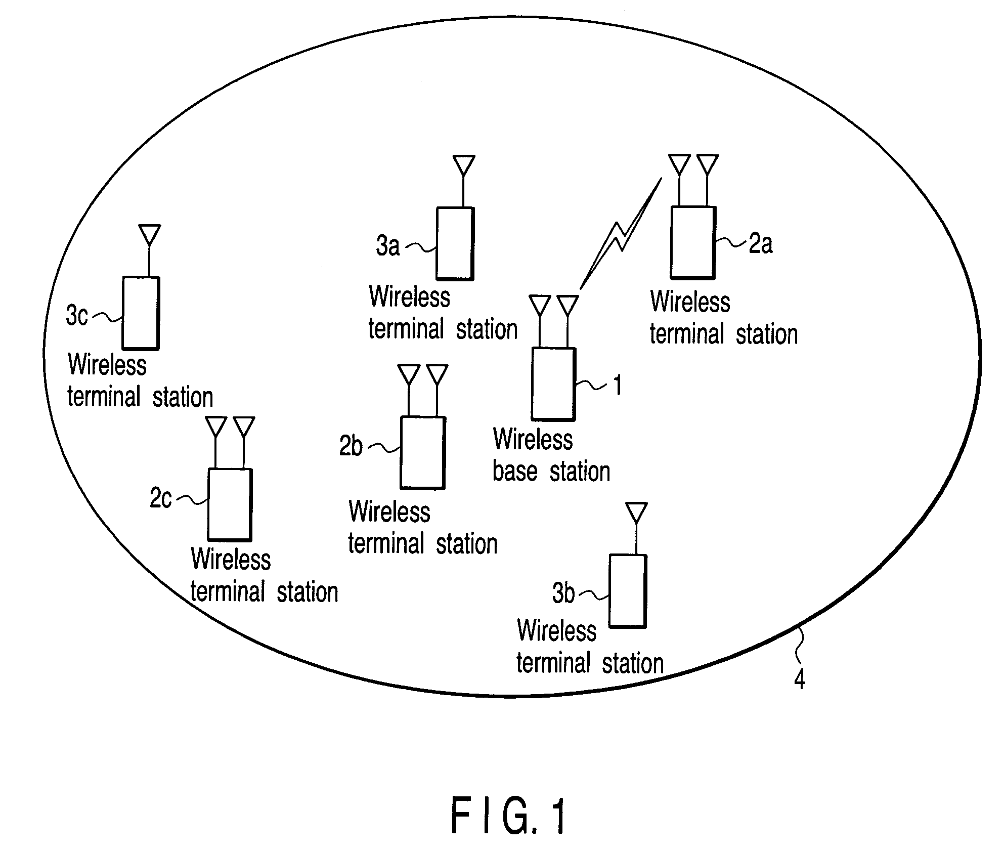
[0102]FIG. 1 is a block diagram showing a wireless communication system according to an embodiment of the present invention. A wireless communication system 4 comprises a wireless base station 1, wireless terminal stations 2a, 2b, and 2c belonging to the first group, and wireless terminal stations 3a, 3b, and 3c belonging to the second group. FIG. 1 shows the three wireless terminal stations 2 belonging to the first group and the three wireless terminal stations 3 belonging to the second group. However, the numbers of wireless terminal stations 2 and wireless terminal stations 3 are not specifically limited.

[0103]The wireless base station 1 allows the wireless terminal station 2 belonging to the first group and the wireless terminal station 3 belonging to the second group to perform wireless communication between them while sharing two different frequency channels. In the wireless communication system 4, one of the wireless terminal stations 2 belonging to the first group and one of...

second embodiment

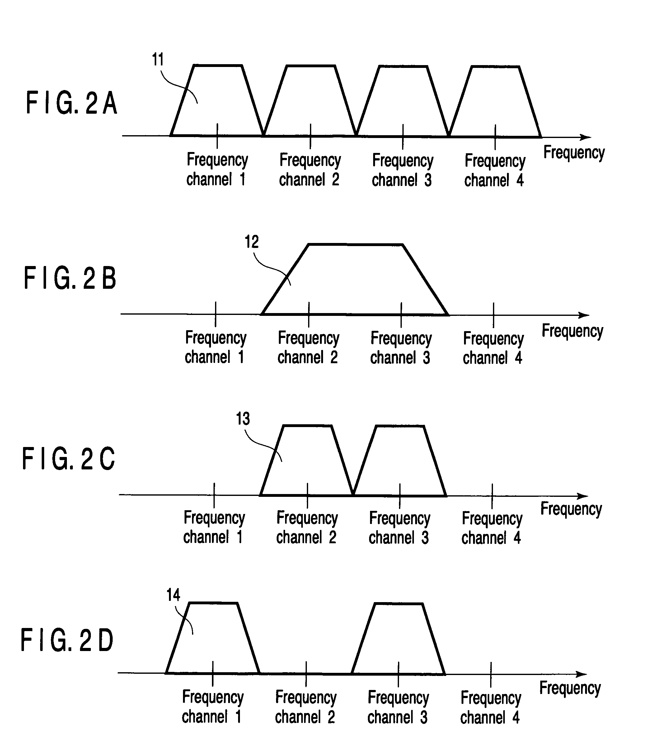
[0110]FIG. 5 is a view showing the second example of the packet transmission / reception timing in this embodiment. Referring to FIG. 5, reference numeral 21 denotes a communication period in which the 40-MHz bandwidth is used; 22, a communication period in which the 20-MHz bandwidth is used; 23, a packet transmitted by a wireless base station 1 in FIG. 1; 24, a packet transmitted by a wireless terminal station 2 belonging to the first group in FIG. 1; and 41, a packet transmitted by a wireless terminal station 3 belonging to the second group. Assume that in this case, the wireless terminal station 2 belonging to the first group in FIG. 1 can perform communication using the 40-MHz bandwidth and freely switch the frequency channels shown in FIGS. 2A to 2D without any instruction from the wireless base station 1. Assume that the wireless terminal station 3 belonging to the second group in FIG. 1 can perform only communication using the 20-MHz bandwidth and can switch frequency channels ...

third embodiment

[0120]FIG. 7 is a view showing the third example of the packet transmission / reception timing in this embodiment. Referring to FIG. 7, reference numeral 21 denotes a communication period in which the 40-MHz bandwidth is used; 22, a communication period in which the 20-MHz bandwidth is used; 23, a packet transmitted by a wireless base station 1 in FIG. 1; 24, a packet transmitted by a wireless terminal station 2 belonging to the first group in FIG. 1; 41, a packet transmitted by a wireless terminal station 3 belonging to the second group; 61, a packet containing information indicating the permission of direct communication which the wireless base station 1 transmits; and 62, a packet transmitted before the wireless base station 1 transmits a packet containing information indicating the permission of direct communication in a communication period in which the 20-MHz bandwidth is used. Assume that in this case, as in the second embodiment, the wireless terminal station 2 belonging to th...


PUM


Abstract

In a wireless communication system having a wireless base station, wireless terminal stations belonging to a first group which performs wireless communication while sharing different frequency channels, and wireless terminal stations belonging to a second group which performs wireless communication by using one frequency channel, a first communication period and a second communication period is alternately repeated. In this system, a wireless terminal station belonging to the first or the second group communicates with the wireless base station by using a first frequency channel in the first communication period. Direct communication between two wireless terminal stations belonging to the first group by using a second frequency channel without through the wireless base station is performed in the first communication period. Then, a wireless terminal station belonging to the first group communicates with the wireless base station by using both the first and the second frequency channels.

Description

CROSS-REFERENCE TO RELATED APPLICATIONS[0001]This application is based upon and claims the benefit of priority from prior Japanese Patent Application No. 2004-180125, filed Jun. 17, 2004, the entire contents of which are incorporated herein by reference.BACKGROUND OF THE INVENTION[0002]1. Field of the Invention[0003]The present invention relates to a wireless communication method, wireless communication apparatus, and wireless communication system in which a plurality of wireless communication apparatuses perform high-throughput wireless communication while sharing a plurality of different frequency channels.[0004]2. Description of the Related Art[0005]There has been proposed a wireless communication system in which a plurality of wireless communication apparatuses perform high-throughput wireless communication while sharing a plurality of different frequency channels (see Jpn. Pat. Appln. KOKAI Publication No. 2004-23143). In a conventional wireless communication system of this typ...

Claims


Application Information

Patent Timeline
Patent Type & Authority Patents(United States)
IPC IPC(8): H04Q7/20H04L12/28H04W4/06H04W4/10H04W76/02
CPCH04W4/10H04W76/005H04W72/005H04W76/02H04W76/45H04W76/10H04W72/30
Inventor TANDAI, TOMOYAADACHI, TOMOKONAKAJIMA, TETSUUTSUNOMIYA, YORIKONISHIBAYASHI, YASUYUKITAKAGI, MASAHIROTAKEDA, DAISUKESATO, KAZUMI
Owner KK TOSHIBA
Why Eureka
Try Eureka