Carburetor valve control linkage

a technology of valve control and carburetor, which is applied in the direction of carburetor, machine/engine, charge feed system, etc., can solve the problems of losing the acceleration performance of the vehicle, the likelihood of the wheels of the car spinning against the pavement during acceleration, and the mechanic's cumbersome and tedious natur

Inactive Publication Date: 2008-03-18
HOLLEY PERFORMANCE PRODUCTS
View PDF8 Cites 19 Cited by
  • Summary
  • Abstract
  • Description
  • Claims
  • Application Information

AI Technical Summary

Benefits of technology

[0009]Briefly described, the present invention concerns an improved carburetor of a high performance vehicle having a quick change progressive linkage that controls the progressive opening of the butterfly valves of the base plate. The linkage enables the mechanic to expediently and accurately replace the cam installed in the progressive linkage with another cam that might be more desirable for the track conditions where the vehicle is to perform.
[0015]With this arrangement, the mechanic can easily reach the lock pin of the carburetor assembly, withdraw it and thereby disconnecting the closed surface cam from the actuator lever, slide the cam track out over the cam follower of the secondary throttle shaft, and then in reverse order, mount the replacement closed track cam on the actuator lever. This can be performed with little likelihood of hazardous contact with the hot surfaces of the engine and its components, little hazard of losing parts in the engine compartment, and with the assurance of being able to make an accurate and expedient replacement of the closed track cam.

Problems solved by technology

Some high performance engines that are used in race cars have so much power that there is a likelihood of the wheels of the car spinning against the pavement during acceleration.
When the wheels of a vehicle spin, the lost traction between the wheels and the road results in lost acceleration performance of the vehicle.
This is somewhat cumbersome and tedious for the mechanic, and there is a hazard that the screws that connect the parts together may be dropped and lost in the engine of the vehicle, and replacement screws must be used.
Again, this is somewhat cumbersome and tedious to the mechanic, and there is the hazard that the link or pin can be dropped or lost.

Method used


Image

  • Carburetor valve control linkage
  • Carburetor valve control linkage
  • Carburetor valve control linkage

Examples


Embodiment Construction

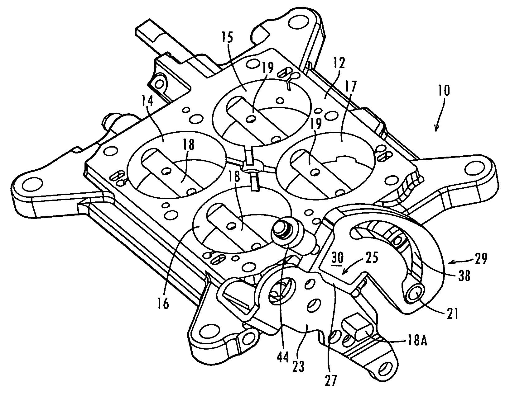
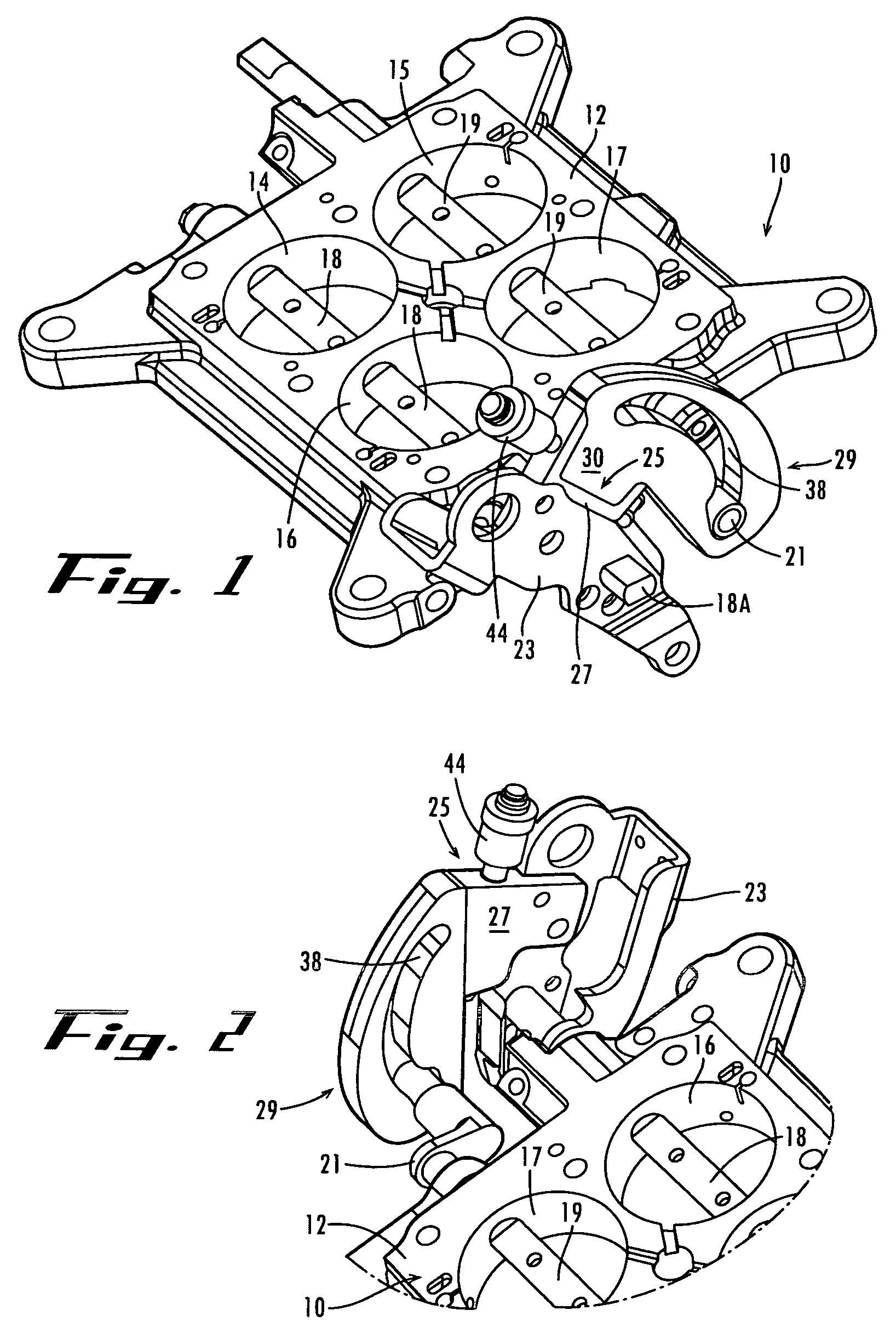
[0022]Referring now in more detail to the drawings, in which like numerals indicate like parts throughout the several views, FIG. 1 illustrates a base plate of a carburetor for mounting the carburetor body on the upper surface 12 of the base plate. The base plate defines four openings 14-17 that register with the Venturi openings (not shown) of the carburetor body. Primary throttle shaft 18 extends through openings 14 and 16 and secondary throttle shaft 19 extends through openings 15 and 17. The distal ends of the throttle shafts 18 and 19 extend beyond the side of the base plate. As shown in FIG. 2, the distal end of secondary throttle shaft 19 is formed with a crank linkage 21.

[0023]Actuator lever 23 is mounted to the flattened end portion 18A of the primary throttle shaft 18 so that when the actuator lever 23 is rotated about the primary crank linkage, it rotates the crank linkage. Butterfly valves (not shown) are mounted to the flats of the primary throttle shaft 18 within the o...


PUM


Abstract

A carburetor for a high performance vehicle includes an actuator lever mounted to a first valve linkage for rotating a first pair of carburetor butterfly valves and a crank mounted to a second valve linkage for rotating a second pair of carburetor butterfly valves, a cam mounted on the actuator lever for engaging and moving said crank and rotating said second pair of valves in response to the movement of the actuator lever, and a quick disconnect coupling between said actuator lever and said cam such that the cam is removable from said actuator lever and can be replaced by another cam.

Description

CROSS-REFERENCE TO RELATED APPLICATION[0001]This application claims priority to now abandoned U.S. provisional application entitled, “Carburetor Valve Control Linkage,” having Ser. No. 60 / 667,961, filed Apr. 4, 2005, which is entirely incorporated herein by reference.FIELD OF THE INVENTION[0002]This invention concerns carburetors for engines of high performance vehicles, such as race cars that perform on oval tracks. More particularly, this invention concerns a four barrel carburetor with a progressive linkage for controlling the movement of the secondary butterfly valves.BACKGROUND OF THE INVENTION[0003]Some high performance engines that are used in race cars have so much power that there is a likelihood of the wheels of the car spinning against the pavement during acceleration. When the wheels of a vehicle spin, the lost traction between the wheels and the road results in lost acceleration performance of the vehicle.[0004]In order to avoid the spinning of the wheels during acceler...

Claims


Application Information

Patent Timeline
Patent Type & Authority Patents(United States)
IPC IPC(8): F02M1/02F02M1/10F02M11/02
CPCF02M11/02
Inventor GRANT, BARRY S.ALM, SCOTT B.
Owner HOLLEY PERFORMANCE PRODUCTS
Why Eureka
Try Eureka