Two-cycle engine with forward scavenging air positioning and single-flow carburetor

Inactive Publication Date: 2005-05-10
ANDREAS STIHL AG & CO KG
View PDF12 Cites 29 Cited by
  • Summary
  • Abstract
  • Description
  • Claims
  • Application Information

AI Technical Summary

Problems solved by technology

In practice, a number of problems occur during the metering of the...

Method used


Image

  • Two-cycle engine with forward scavenging air positioning and single-flow carburetor
  • Two-cycle engine with forward scavenging air positioning and single-flow carburetor
  • Two-cycle engine with forward scavenging air positioning and single-flow carburetor

Examples


Embodiment Construction

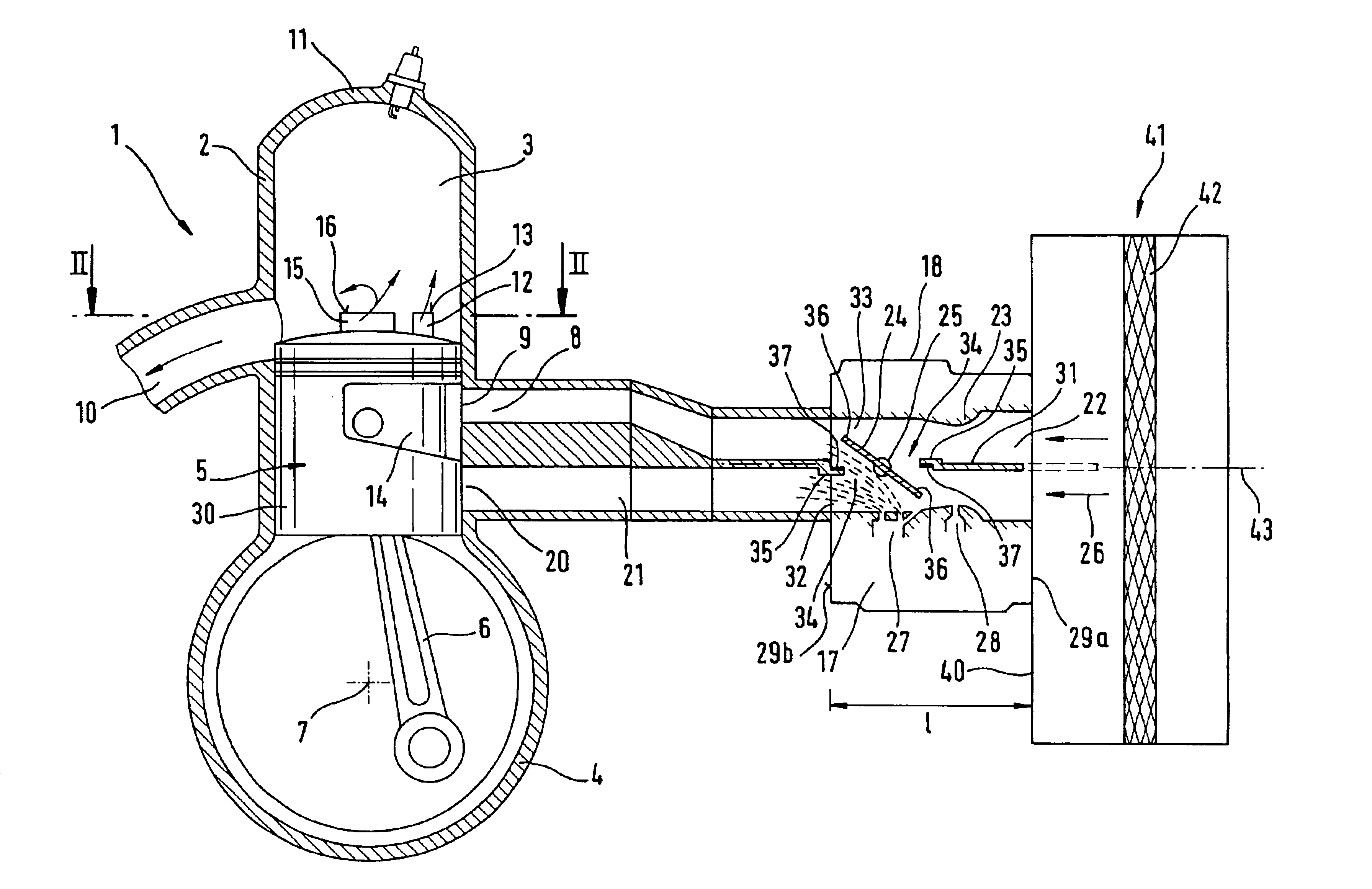
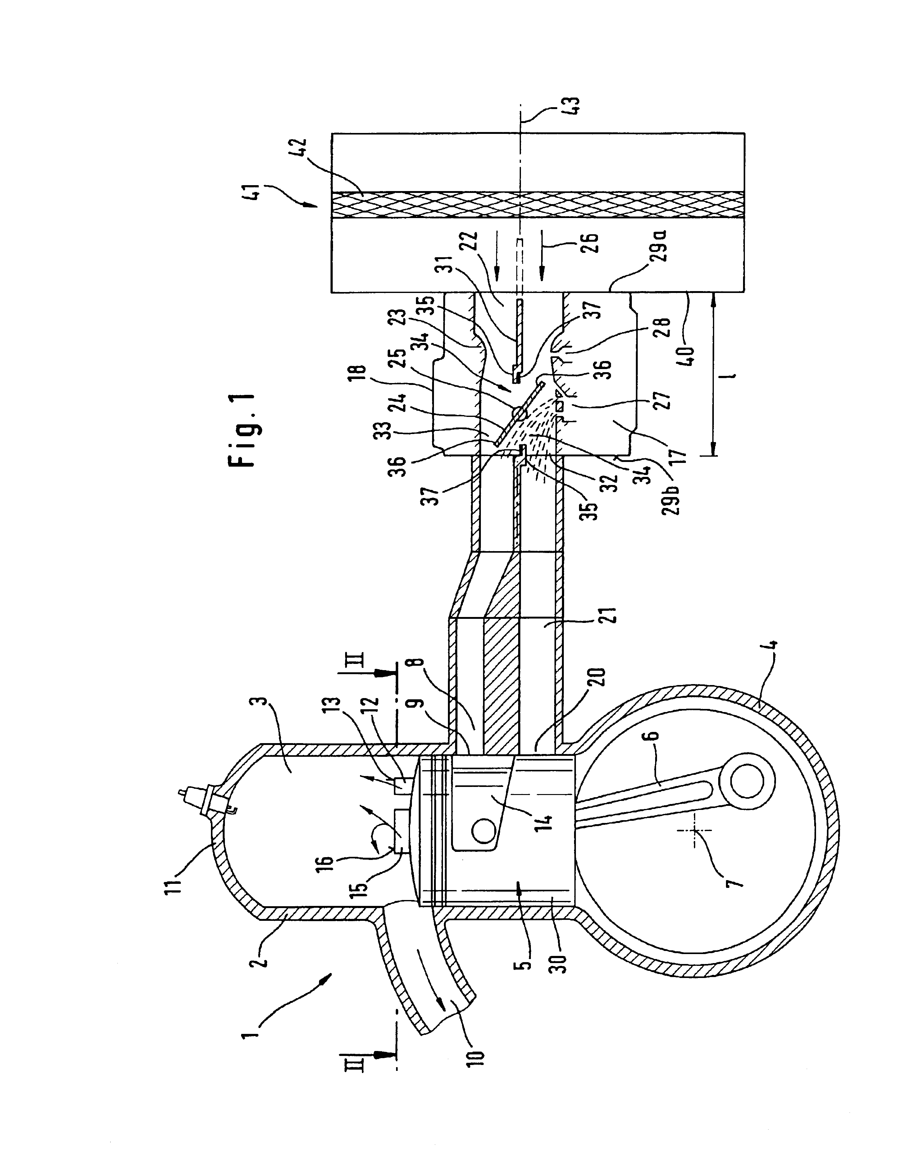
[0016]The two-cycle engine 1 illustrated schematically in FIG. 1 is used as a small-volume drive engine preferably in manually operated, portable tools such as, for example, chain saws, brush cutters, parting-off grinders, etc. The displacement of an internal combustion engine of this type lies within a range of 18 cm3 and 500 cm3.

[0017]The two-cycle engine 1 has a cylinder 2 in which is provided a combustion chamber 3 which is delimited by a reciprocating piston 5. Via a connecting rod 6, the piston 5 drives a crankshaft 4 which is mounted in a crankcase 4 in such a manner that it can rotate.

[0018]An inlet 20, which in the illustrated embodiment is controlled by the piston skirt 30 opens into the crankcase 4. In the embodiment shown, the inlet 20 is therefore opened and closed dependent upon the stroke position of the piston 5. It can be useful to provide a membrane or diaphragm control system instead of the piston port control system illustrated. The inlet 20 then opens into the c...


PUM


Abstract

A two-cycle engine having forward scavenging is provided. Mixture drawn into the crankcase via a butterfly valve carburetor is conveyed into a combustion chamber via transfer channels in the cylinder. An air duct is connected via a controllable connection with a transfer channel to supply essentially fuel-free air thereto during a load state of the engine. To convey a fuel quantity adapted to drawn-in air during idling and partial load, yet during full throttle to achieve separated supply of air and mixture, a dividing wall extends in the direction of flow of air in the carburetor intake duct. In the pivot region of the butterfly valve, a connecting aperture in the dividing wall is closed in full throttle by a completely open butterfly valve. During idling and partial load the connecting aperture is open so that a uniform pressure can form in the intake duct in conformity with drawn-in air.

Description

BACKGROUND OF THE INVENTION[0001]The present invention relates to a two-cycle engine, especially as a drive engine in a portable, manually-guided tool or implement such as a power chain saw, a brush cutter, a trimmer, a cut-off machine, etc.[0002]A two-cycle engine of this type is known from DE 199 00 445 A1. A combustion chamber formed in the cylinder is connected to the crankcase via transfer passages, the mixture required for combustion being conveyed to the crankcase. In order to ensure that as-little uncombusted fuel as possible is lost through the exhaust or outlet during the scavenging of the combustion chamber, the transfer passages close to the exhaust are connected to an air duct and fuel-free air is drawn in through the transfer passages during the intake stroke. The air is then held at the front of the transfer passages and enters first the next time the mixture transfers into the combustion chamber. The mixture flowing out of the crankcase follows some time later and th...

Claims


Application Information

Patent Timeline
IPC IPC(8): F02B33/44F02B33/04F02M19/08F02B25/00F02B33/02F02B25/22F02M19/00F02M35/104F02M35/108F02B75/02F02M11/10F02M1/02F02M17/34F02M17/40
CPCF02B25/22F02B33/04F02B33/44F02M35/108F02M19/081F02M35/1019F02B2075/025
Inventor ROSSKAMP, HEIKO
Owner ANDREAS STIHL AG & CO KG
Why Eureka
Try Eureka