
Flexible neck faucet sprayer

a flexible, faucet technology, applied in the direction of spray nozzles, domestic plumbing, pipe elements, etc., can solve the problems of requiring additional force, putting a considerable amount of torque or stress on the faucet, requiring additional force, and putting yet more strain on the faucet and the sprayer/faucet connection

Inactive Publication Date: 2008-03-18
PROTOPLAST
View PDF8 Cites 23 Cited by
  • Summary
  • Abstract
  • Description
  • Claims
  • Application Information

AI Technical Summary

Benefits of technology

[0010]In one aspect the invention provides sprayer for attachment to the spout of a faucet, the sprayer comprising a coupling for releasably securing said sprayer to the spout of a faucet; a spray head through which fluid may be directed for expulsion from said sprayer; and, a neck portion connecting said coupling to said spray head, said neck portion including a passageway permitting the flow of fluid from the spout of the faucet to said spray head, said neck portion flexibly resilient and permitting said spray head to be displaced from a rest position where said spray head is generally aligned with the longitudinal axis of said sprayer to a deflected position where said spray head is deflected from said rest position, said resiliency of said neck portion causing said spray head to be normally biased toward said rest position, said neck portion further including a deflection limiter preventing said spray head from being deflected more than a pre-determined amount from the longitudinal axis of said sprayer.
[0011]In another aspect the invention concerns a sprayer for attachment to the end of a conduit, the sprayer comprising a coupling for releasably securing said sprayer to the end of the conduit; a spray head through which fluid may be directed for expulsion from said sprayer; and, a flexibly resilient neck portion connecting said coupling to said spray head and including an internal passageway permitting the flow of fluid from the conduit to said spray head, said flexibility and resiliency of said neck portion permitting said spray head to be displaced from a rest position where said spray head is generally aligned with the longitudinal axis of said sprayer to a deflected position where said spray head is deflected from said rest position upon the application of a force to either or both of said neck portion and said spray head at an angle to the longitudinal axis of said sprayer, said resiliency of said neck portion causing said spray head to return to said rest position upon removal of said force, said neck portion further including a deflection limiter preventing said spray head from being deflected more than a pre-determined amount from the longitudinal axis of said sprayer.

Problems solved by technology

Although high pressure faucet sprayers provide a number of advantages over previous low pressure devices, currently available faucet sprayers still suffer from a number of inherent limitations.
First, the vertical valving structure that is utilized on most sprayers requires a user to grasp and physically pull down or push up upon the spray head in a vertical plane in order to change from a spray to an aerated flow pattern.
Such movements can put a considerable amount of torque or stress upon the faucet, as well as the faucet / sprayer connection.
Where the hardness of the water is relatively high, mineral deposits within the sprayer body can make it difficult to switch between a spray and an aerated flow pattern, thereby requiring the application of additional force and putting yet further strain upon the faucet and the sprayer / faucet connection.
Mineral deposits also tend to accumulate on ball and socket or swivel joints making them difficult to operate.
Currently available faucet sprayers also provide only a limited ability for moving the spray head relative to the faucet and angling the discharge away from a vertical plane.
To some degree a double ball and socket structure increases the ability to direct the spray further from a vertical plane, however, only at the expense of a more complicated mechanical structure, increased cost, and even greater susceptibility to the negative effects of hard water.

Method used


Image

  • Flexible neck faucet sprayer
  • Flexible neck faucet sprayer
  • Flexible neck faucet sprayer

Examples


Embodiment Construction

[0027]The present invention may be embodied in a number of different forms. However, the specification and drawings that follow describe and disclose only some of the specific forms of the invention and are not intended to limit the scope of the invention as defined in the claims that follow herein.

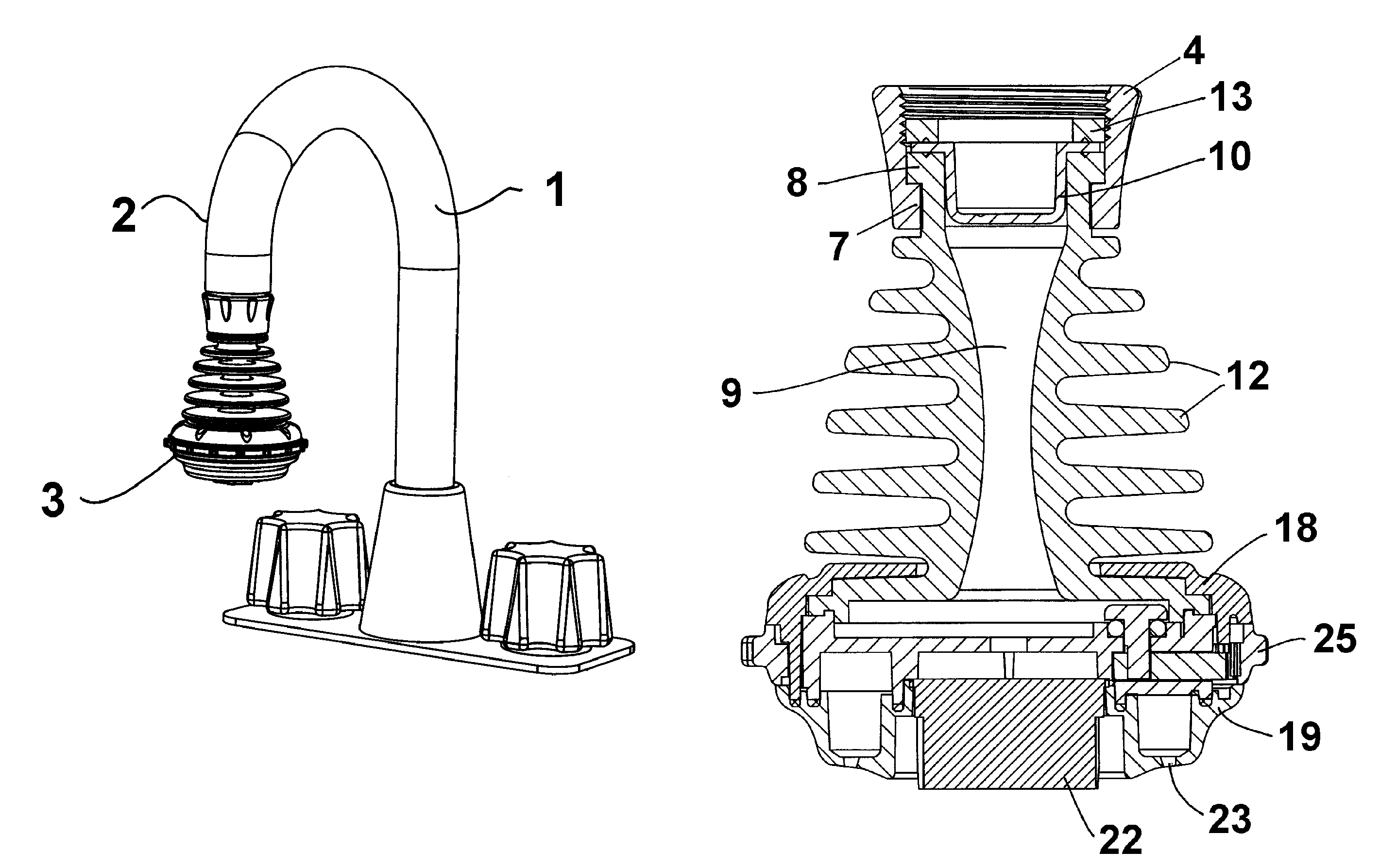
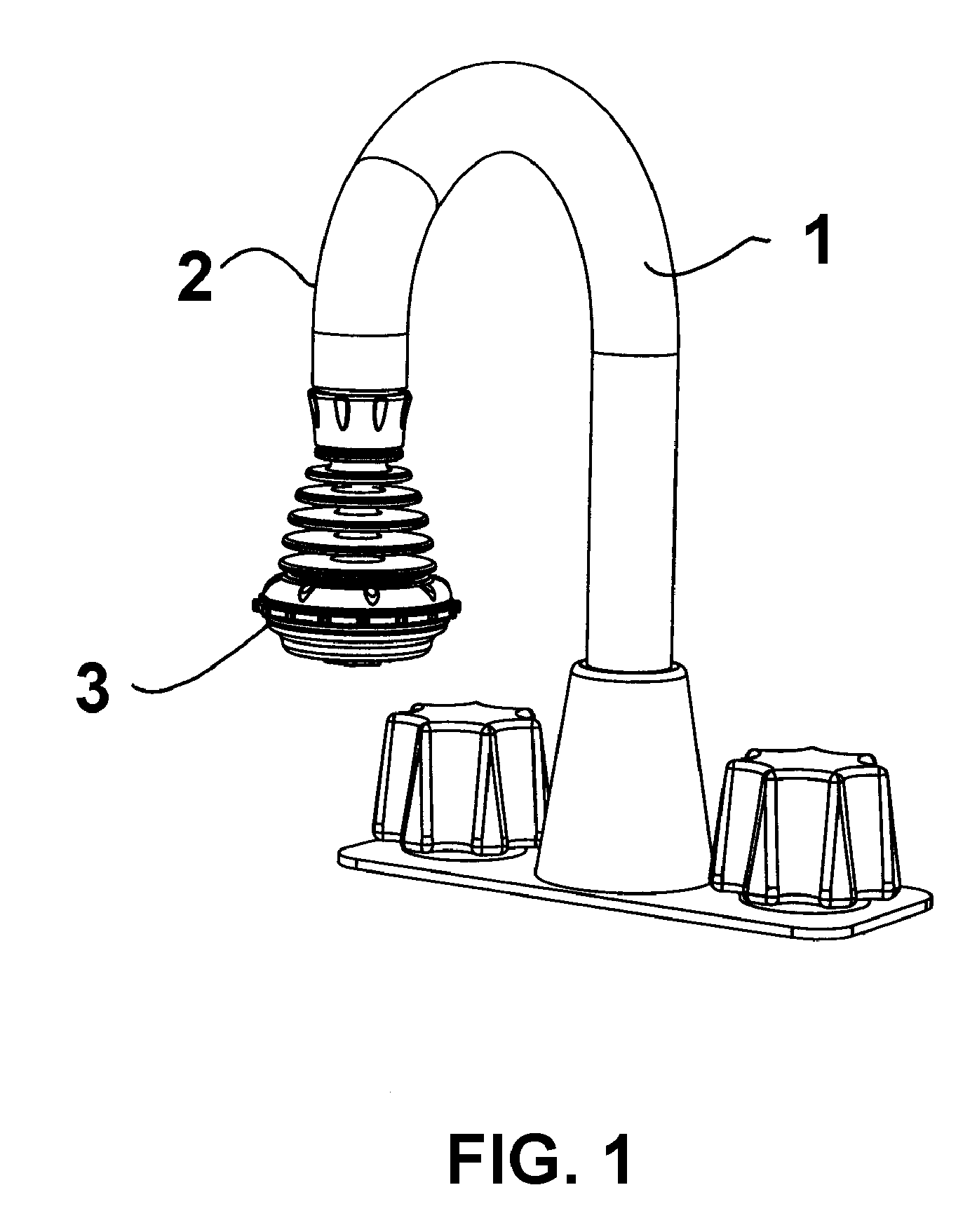
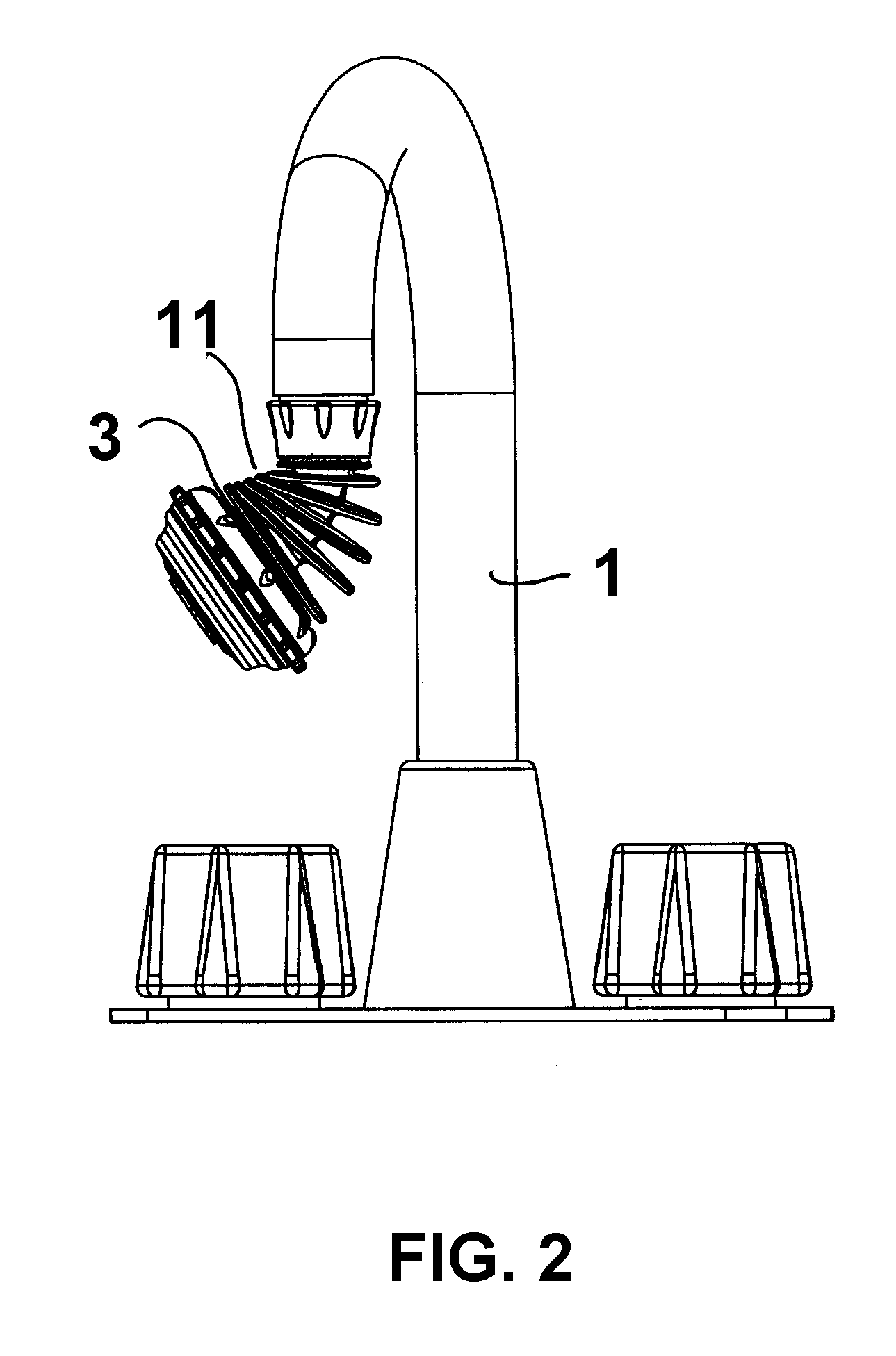
[0028]In FIG. 1 there is shown a typical or generic form of faucet 1 having a spout 2 that has attached to its end a sprayer 3 constructed in accordance with one of the preferred embodiments of the present invention. Sprayer 3 is formed generally from a coupling 4, a spray head 5 and a neck portion 6 that connects coupling 4 to spray head 5. Sprayer 3 in FIG. 1 is shown as it would appear normally in a rest position wherein the coupling, neck portion and spray head all lie along the same general longitudinal axis. In FIGS. 2 and 3 the spray head has been deflected away from the longitudinal axis of the sprayer.

[0029]As shown in the attached drawings, coupling 4 serves the purpose of provi...


PUM


Abstract

A sprayer for attachment to the spout of a faucet. The sprayer comprises a coupling, a spray head through which fluid may be directed for expulsion and a neck portion. The coupling releasably secures the sprayer to the spout of a faucet. The neck portion connects the coupling to the spray head and includes a passageway permitting the flow of fluid from the spout of the faucet to the spray head. The neck portion is flexibly resilient and permits the spray head to be displaced from a rest position where it is generally aligned with the longitudinal axis of the sprayer to a deflected position where it is deflected from its rest position. The resiliency of the neck portion causes the spray head to be normally biased toward its rest position. The neck portion further includes a deflection limiter preventing the spray head from being deflected more than a pre-determined amount from the longitudinal axis of the sprayer.

Description

FIELD OF THE INVENTION[0001]This invention relates to faucet sprayers and in particular to a unique flexible neck faucet sprayer.BACKGROUND OF THE INVENTION[0002]Sprayers or sprayer attachments are widely used on the faucets of kitchen sinks, washroom lavoratories, laundry room sinks and for a wide variety of other applications. Generally faucet sprayers are threaded or otherwise attached to the spout of a faucet to allow a user to adjust the faucet discharge from a stream, which may include an aerated stream, to a spray, or a combination of a stream and a spray.[0003]The first significant introduction of faucet sprayers into the marketplace occurred in or around the late 1940's. At that time various manufacturers offered a flexible rubber sprayer that could be press-fit onto the end of an unthreaded faucet spout. Somewhat later the same sprayer was supplied with a threaded coupling that allowed it to be threaded onto the end of faucets having either internal or external threads.[00...

Claims


Application Information

Patent Timeline
IPC IPC(8): B05B15/08B05B15/68
CPCB05B1/1627B05B15/066E03C1/08B05B1/18E03C2001/082Y10S239/12B05B15/652
Inventor TRACY, MARTINCOLPITTS, PETER
Owner PROTOPLAST
Features
  • Generate Ideas
  • Intellectual Property
  • Life Sciences
  • Materials
  • Tech Scout
  • Unparalleled Data Quality
  • Higher Quality Content
  • 60% Fewer Hallucinations
Learn More