

Drag system for a spinning reel
a technology of dragging system and spinning reel, which is applied in the direction of reels, applications, fishing, etc., can solve the problems of imposing certain precision constraints on the manufacturing of spools, and achieve the effect of increasing the effective drag area of the reel drag system and reducing the dimensional constraints on spool siz
Active Publication Date: 2008-03-18
PURE FISHING
View PDF9 Cites 6 Cited by
- Summary
- Abstract
- Description
- Claims
- Application Information
AI Technical Summary
Benefits of technology
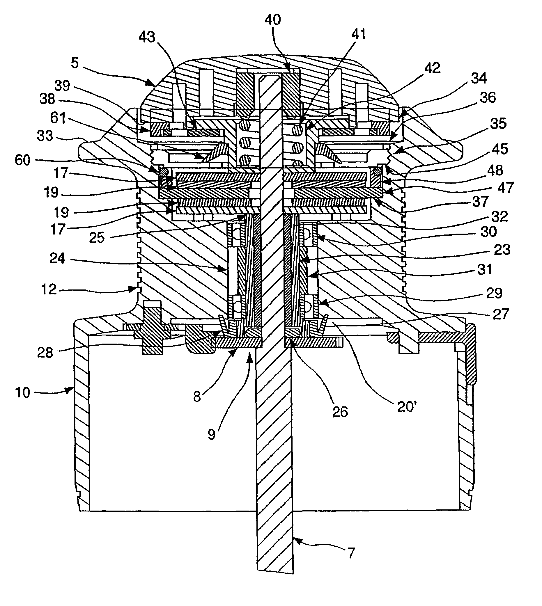
The invention is a spinning reel with a drag system that avoids the use of a small drag washer below the spool and increases the effective drag area of the reel drag system. The spool assembly is mounted to its spindle and includes a keyed shape on the proximal end of the spindle washer and a circular shape on the distal end of the spindle, furthest from the drag knob. The spool is radially and axially drivable by a spindle through at least one spindle washer and at least one spool washer that have one or more frictional drag washers therebetween. The spool assembly has a plurality of spindle, friction, and spool washers for retarding the movement of the spool due to interacting structures on the washers and retaining ring that engage the interior of the spool. The invention allows for a larger effective frictional surface area for controlling the rotation and counter-rotation of the spool assembly and accommodates torque effects of line tension further from the centerline axis of the spool.
Problems solved by technology
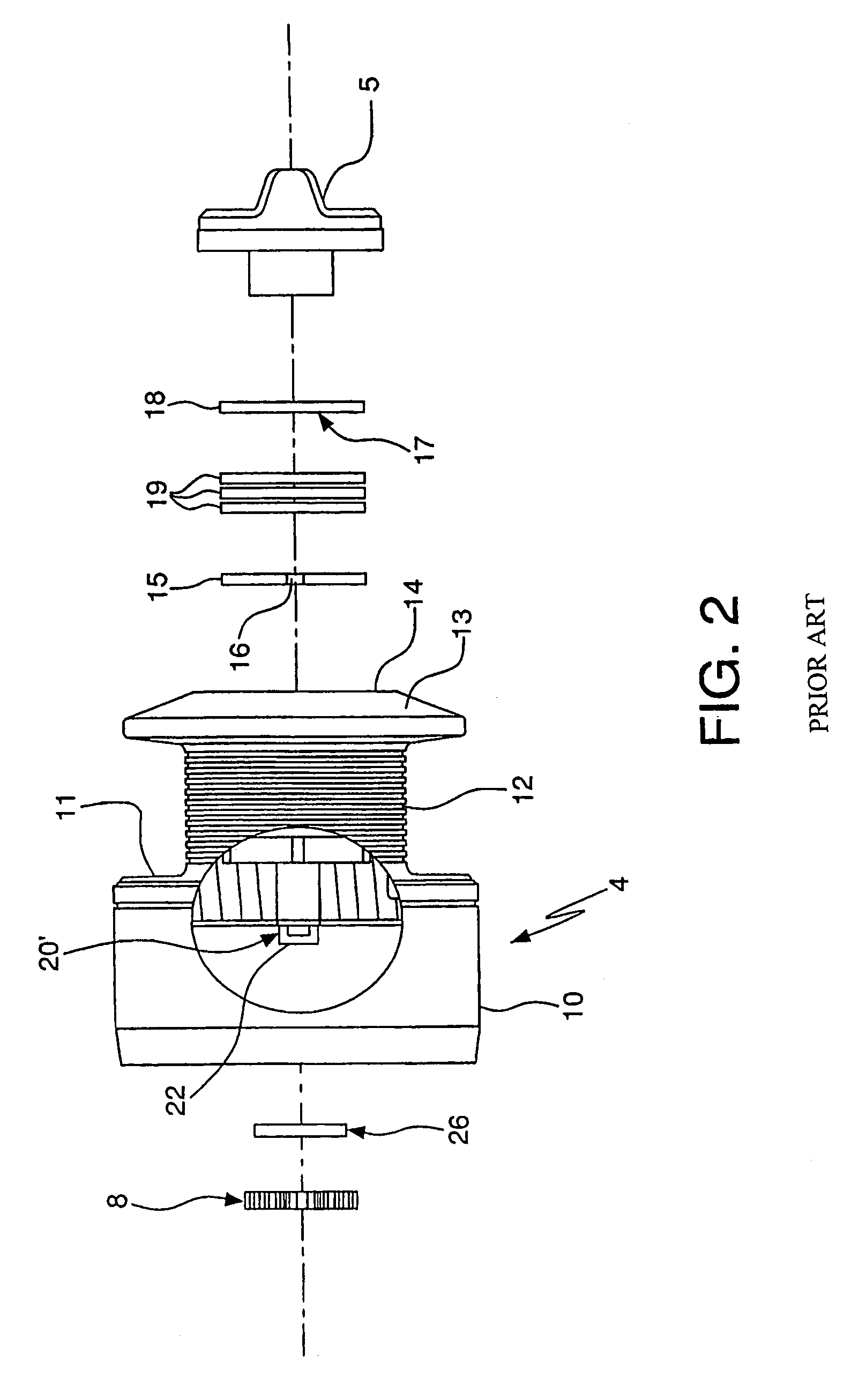
This need for separated but parallel surfaces imposes certain precision constraints on the manufacturing of the spool.
Method used
View moreImage
Smart ImageViewing Examples

Examples
second embodiment
[0048]Turning to FIG. 5, in a second embodiment, engaging ring 48′ exhibits projections 50′ and slots 51, both are preferably rectangular as shown, for engaging spool washers 46, 47′ and spaced equally.
third embodiment
[0049]In the present invention, referred to in FIG. 7, the engaging ring and the front spool flange are integrally formed in spool cover 44′. Spool cover 44′ exhibits projections 50″ for structurally engaging spool washer 47′ and thru holes 55. Spool 4′ exhibits threaded receivers 56 that are disposed substantially uniformly around rim 59 of spool 4′. Spool cover 44′ is attached to spool 4′ using fasteners, such as bolts, that engage cover 44′, extend through thru holes 54 and into threaded receivers 56.
Login to View More PUM
 Abstract
A drag mechanism for a spinning reel for providing frictional resistance to the rotation of the spool of a spinning reel. The spinning reel includes a body having a rotor assembly coupled to the main body for rotating about a central axis. A crank handle is connected to the body for rotating the rotor assembly and oscillating a spindle passing through the rotor assembly. A spool assembly is disposed upon the spindle and defined by engageable structural features on the interior surface of a drag stack chamber to couple with spool washers having correspondingly matable engagement features. A drag knob assembly is connected to the spool assembly opposite the rotor assembly for controlling axial friction forces within the drag stack chamber and counter-rotation friction of the spool relative to the spindle. At least one spool washer is fixedly attached to the spool to provide a drag system for spinning reels that is more effective and with greater control.
Description
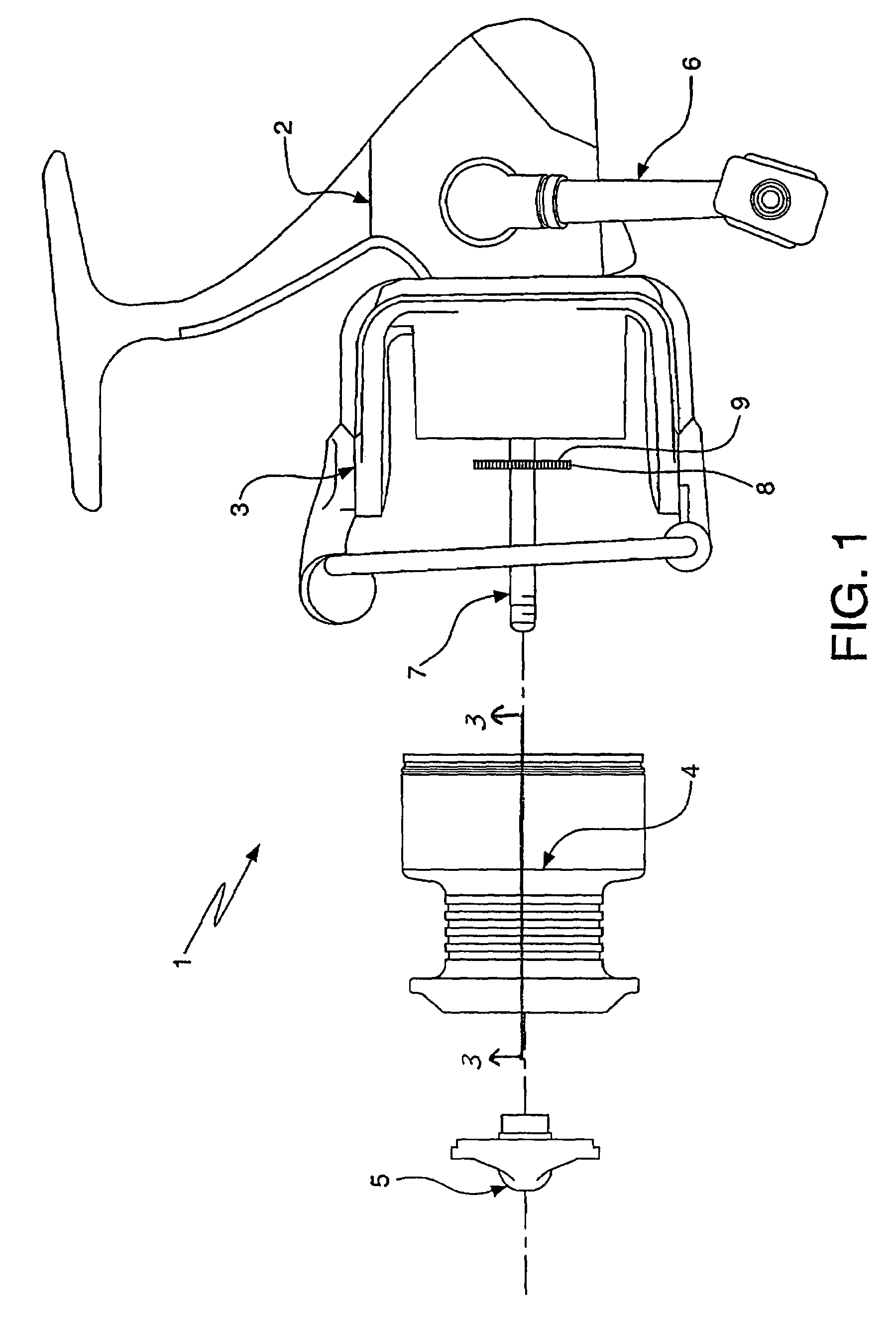
FIELD OF THE INVENTION[0001]The present invention relates to a drag system capable of providing frictional resistance to the rotation of the spool of a spinning reel. More particularly, the invention relates to a fishing reel having an oscillating spool whose rotation with respect to a spindle is frictionally retarded by a drag system.BACKGROUND OF THE INVENTION[0002]Conventional spinning reels used for fishing generally include a body, a rotatable crank handle extending from the body, and a rotor assembly rotatably supported on the body and geared to the crank handle. When the rotor is turned, the line is retrieved and wrapped around a line wrapping section of a spool mounted to a spindle that protrudes through the rotor assembly. To protect the line from excessive tension forces from a strong or determined fish (or other high tension loads), the spinning reel is equipped with a drag system which frictionally retards the rotation of the spool relative to the rotor assembly unless a...
Claims
Login to View More Application Information
Patent Timeline
 Patent Type & AuthorityPatents(United States)
IPC IPC(8): A01K89/01
CPCA01K89/0111A01K89/027A01K89/03
InventorIVIE, CAMERON R.
OwnerPURE FISHING