Temperature sensor

a temperature sensor and sensor technology, applied in the field of temperature sensors, can solve the problems of short service life of the temperature regulator, material fatigue of the contact spring, and simultaneous occurrence of critical loads, and achieve the effects of minimal fatigue, optimal transmission, and enlargement of the metallic surfa

Active Publication Date: 2008-03-18
EIKA S COOP LTDA +1
View PDF26 Cites 8 Cited by
  • Summary
  • Abstract
  • Description
  • Claims
  • Application Information

AI Technical Summary

Benefits of technology

[0013]Through the measures suggested, it is ensured that the contact spring is clamped between the rod and the support that the spring is applied to. The contact spring is brought into its open position, in the event of an appropriate increase of the temperature, by the spring applied to the support. It is therefore possible to elastically pre-tension the contact spring in the cold state of the temperature sensor, the mechanical tension in the contact spring being reduced with increasing temperature. At the same temperature and / or current load, compared with the known solution of the indirect snap mechanism, a significantly reduced tension load of the contact spring results, since the spring supported on the support assumes tasks which the contact spring must assume itself in the known solution. This has a positive effect on the material fatigue.
[0022]According to another feature of the present invention, the region of the wave bow may be protected from deformations by an additional fitted metal rod.

Problems solved by technology

In operation, this results in a simultaneous occurrence of critical loads.
These include both externally supplied temperature and the intrinsic heating of the spring because of the electrical load, as well as mechanical tensions, which leads to material fatigue of the contact spring and therefore to a short service life of the temperature regulator.
Furthermore, this high load of the contact spring also leads to failure of the snap mechanism.
The thread quality of the internal thread provided on the external tube may only be fixed within coarse tolerances because of the tube material, which is difficult to shape, this having the effect that the wear of the threading tool is very high and occurs rapidly.
The poor thread quality relates above all to the thread flanks and the tolerance deviations of the thread core diameter.
With the simultaneous occurrence of the mechanical load required for the pre-tension of the additional spring element, these loads lead to the same damage picture which is to be observed in the contact spring.
The contact spring is thus strained to the carrying capacity and beyond, frequently repeated strains, such as cyclic strains, leading to irreversible material changes even if the mechanical tensions in the contact spring are below the yield strength.

Method used


Image

  • Temperature sensor
  • Temperature sensor
  • Temperature sensor

Examples


Embodiment Construction

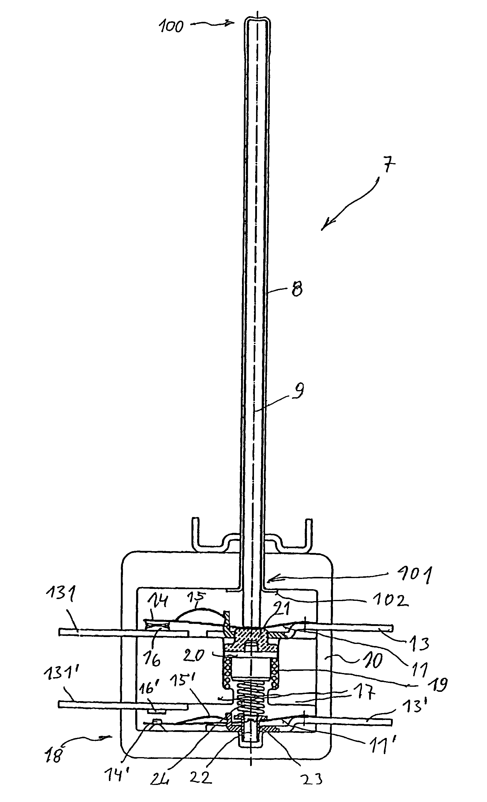
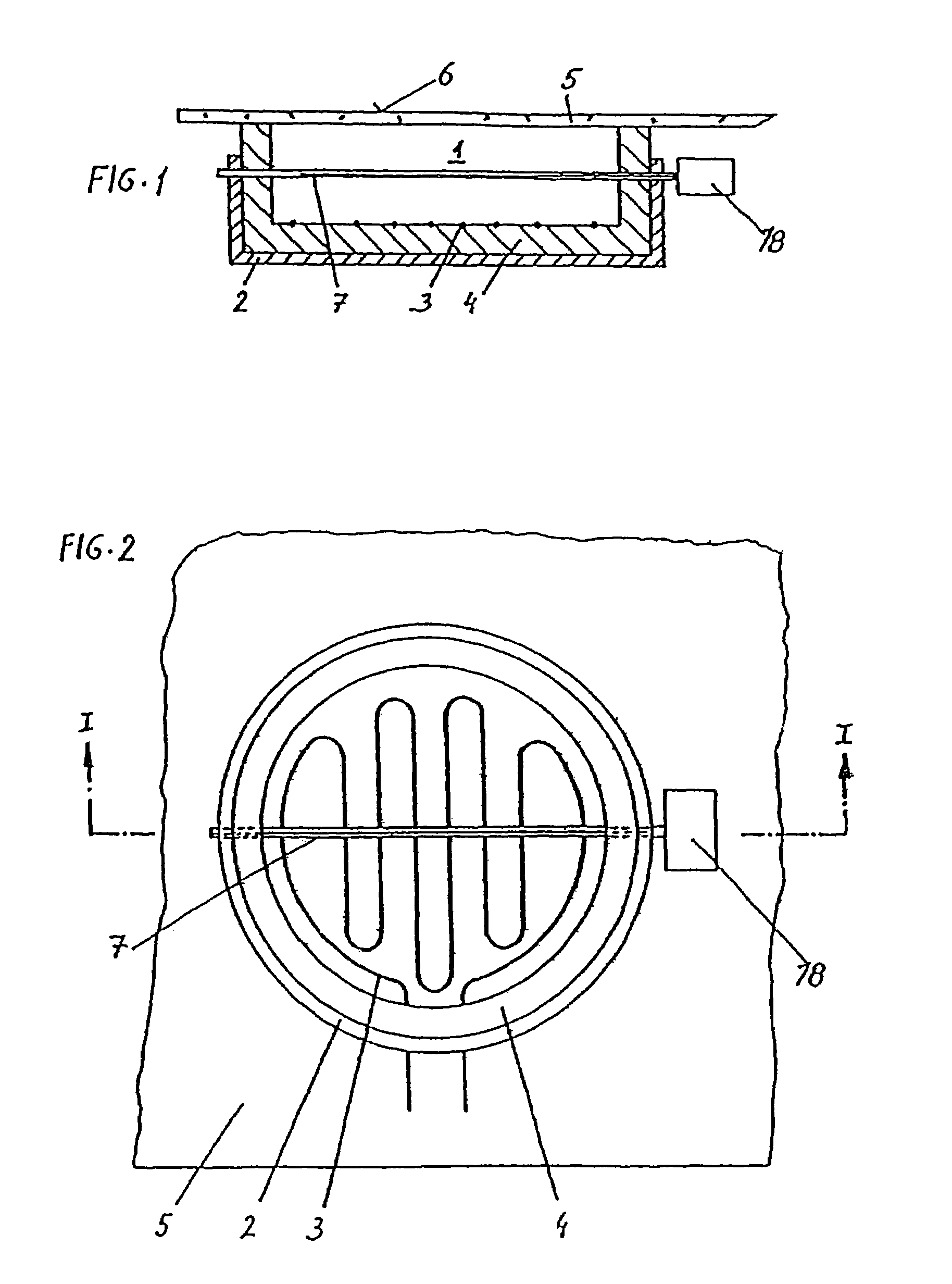
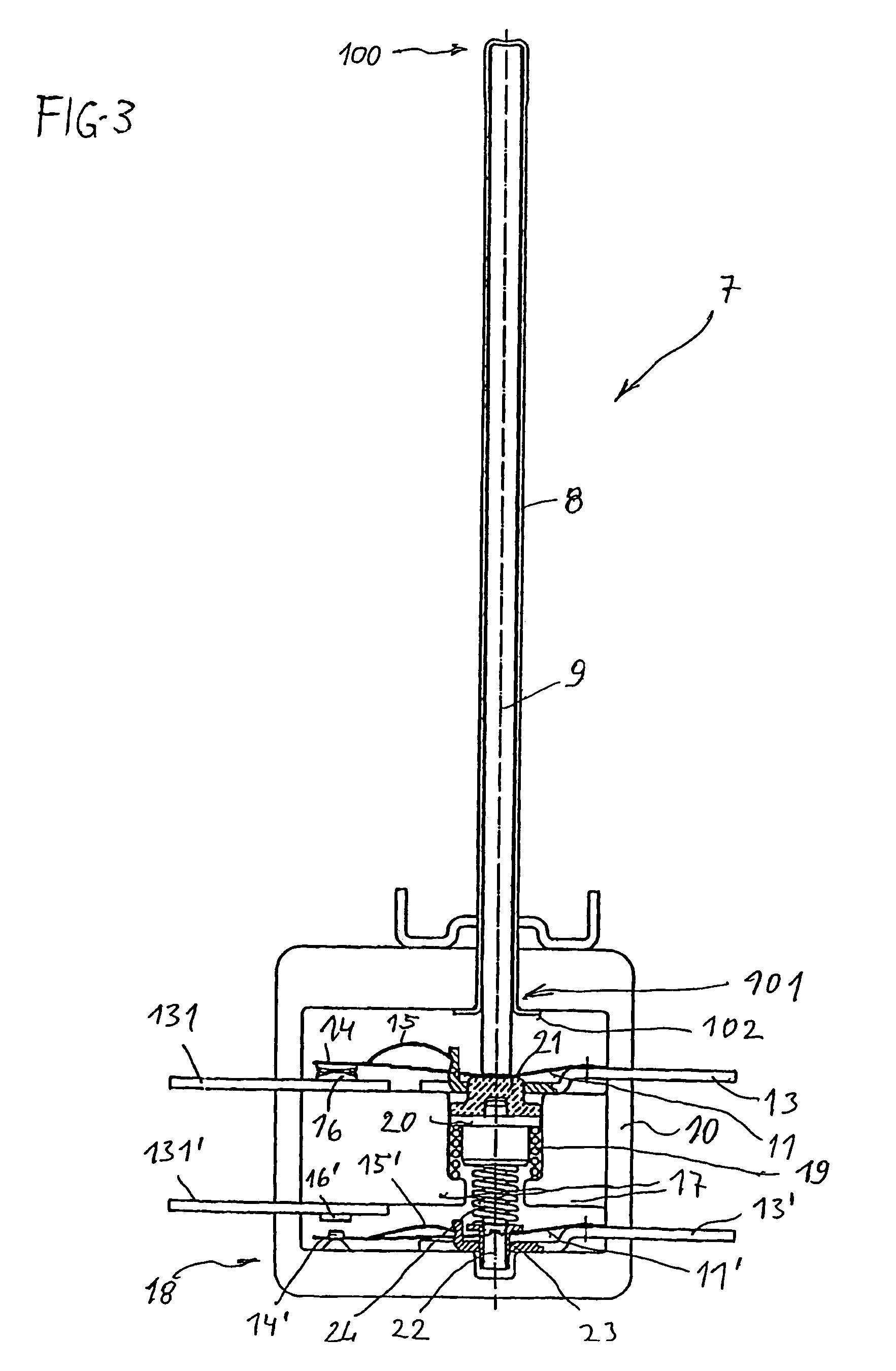
[0032]Throughout all the Figures, same or corresponding elements are generally indicated by same reference numerals. These depicted embodiments are to be understood as illustrative of the invention and not as limiting in any way. It should also be understood that the drawings are not necessarily to scale and that the embodiments are sometimes illustrated by graphic symbols, phantom lines, diagrammatic representations and fragmentary views. In certain instances, details which are not necessary for an understanding of the present invention or which render other details difficult to perceive may have been omitted.

[0033]Turning now to the drawing, and in particular to FIG. 1, there is shown a radiant heating element 1 having a trough 2, in which a spiral-laid heating coil 3 is located that is embedded in an embedding compound 4 (see FIGS. 1 and 2). The radiant heating body 1 is positioned below a plate 5 made of metal, glass ceramic, or the like, that forms a cooking area 6. A temperatu...


PUM


Abstract

A temperature sensor for a radiant heating element includes a first expansion element, e.g., a tube, connected to a housing of a switch, which is permanently connected to a second expansion element, e.g., a rod in the region of its free end. The two expansion elements have different thermal expansion coefficients, and the switch has at least one contact spring, which is pre-tensioned against a point and carries a contact. The contact spring is implemented as a snap spring. The first expansion element has a spring acting in its axial direction applied to it. To avoid rapid fatigue of the contact spring, the second expansion element acts on the contact spring on one side and the spring acting in the axial direction of the second expansion element acts on the contact spring on the other side, with the spring acting against the second expansion element via a support.

Description

CROSS-REFERENCES TO RELATED APPLICATIONS[0001]This application claims the priority of European Patent Application, Serial No. 04004151.9, filed Feb. 24, 2004, pursuant to 35 U.S.C. 119(a)-(d).BACKGROUND OF THE INVENTION[0002]The present invention relates to a temperature sensor for a radiant heating element, this temperature sensor having an expansion element, such as a tube, connected to a housing of a switch, which is permanently connected to a further expansion element, such as a rod, in the region of its free end, the two expansion elements having different thermal expansion coefficients, and the switch having at least one contact spring, pre-tensioned against a point and carrying a contact, which is implemented as a snap spring and a spring, which acts in its axial direction, being applied to one of the expansion elements.[0003]Temperature sensors of this type are generally used, for example, where electrically or gas heated devices, such as hot plates, radiant heating elements...

Claims


Application Information

Patent Timeline
Patent Type & Authority Patents(United States)
IPC IPC(8): H01H37/48H01H37/32H01H37/20
CPCH01H37/48H01H37/20
Inventor LOSBICHLER, PAULAURADNIK, CHRISTIAN
Owner EIKA S COOP LTDA
Why Eureka
Try Eureka