Survey system capable of remotely controlling a surveying instrument

a technology of remote control and surveying instruments, applied in the field of surveying systems, can solve the problem of inability to perform automatic collimation, and achieve the effect of reducing the time required for performing automatic collimation

Active Publication Date: 2008-03-18
KK TOPCON
View PDF7 Cites 52 Cited by
  • Summary
  • Abstract
  • Description
  • Claims
  • Application Information

AI Technical Summary

Benefits of technology

[0009]The present invention has been made in consideration of the above-mentioned problem, and it is an object of the present invention to provide a survey system in which guide light is emitted from the side of a target, and, on the side of a surveying instrument, a telescope is directed roughly toward the target by receiving the guide light so that time required to perform automatic collimation can be shortened, wherein the automatic collimation can be reliably performed by removing guide light reflected by reflective objects such as windowpanes.

Problems solved by technology

Therefore, disadvantageously, cases may arise in which a malfunction occurs in collimation preparation prior to the start of automatic collimation, and the automatic collimation cannot be performed.

Method used


Image

  • Survey system capable of remotely controlling a surveying instrument
  • Survey system capable of remotely controlling a surveying instrument
  • Survey system capable of remotely controlling a surveying instrument

Examples


Embodiment Construction

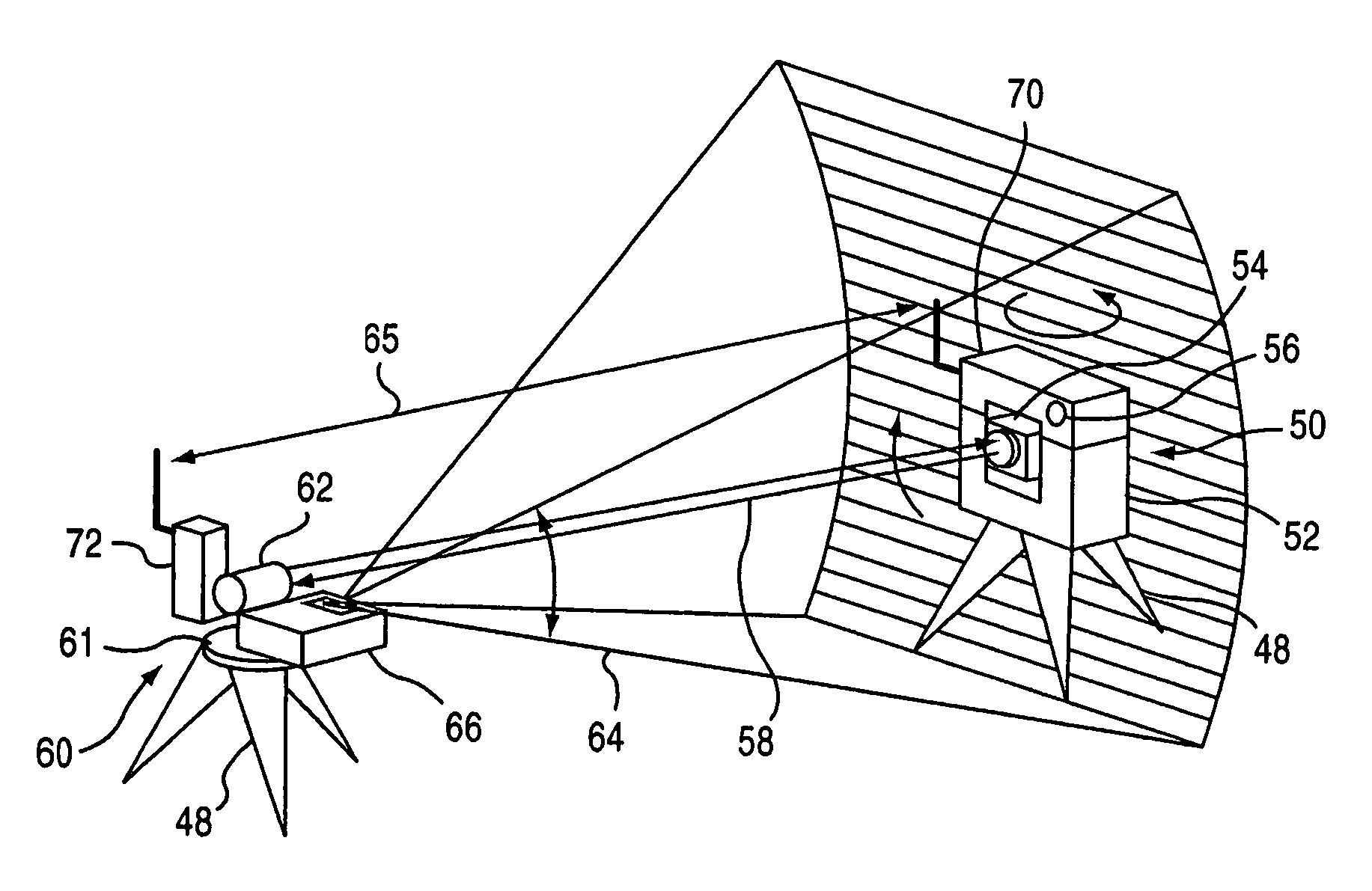
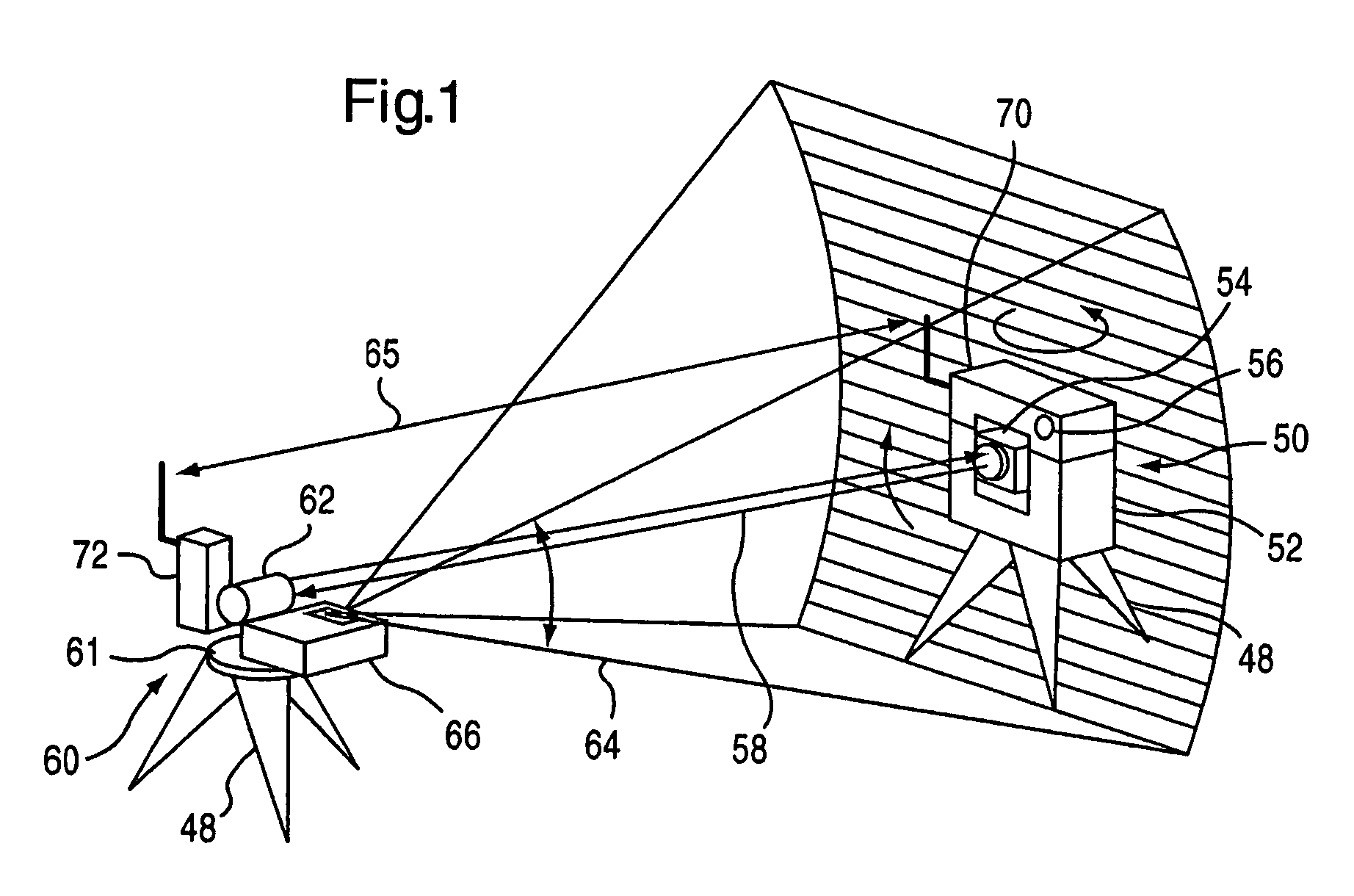
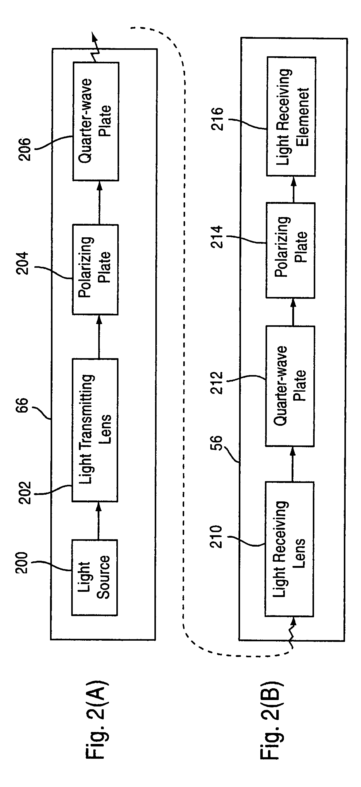
[0021]According to the invention, when circularly polarized guide light emitted from the guide light transmitter is reflected by a reflective object existing behind the surveying instrument, the circularly polarized guide light is changed into circularly polarized reflection guide light whose rotational direction has been reversed. When guide light that directly enters the direction detector from the guide light transmitter passes through the polarization changing portion, the guide light is changed into linearly polarized light, and can pass through the polarizing plate. However, when the reflection guide light whose rotational direction has been reversed passes through the polarization changing portion, the reflection guide light is changed into linearly polarized light whose polarization plane is deviated by 90° in comparison to that obtained when the circularly polarized light having the original rotational diction passes through the polarization changing portion, so that the Li...


PUM


Abstract

In a survey system in which guide light is emitted from the side of a target, and, on the side of a surveying instrument, a telescope is directed roughly toward the target by receiving the guide light so as to shorten the time required for automatic collimation, the automatic collimation of the surveying instrument can be reliably performed by removing guide light reflected by reflective objects such as windowpanes. The target has a guide light remitter that emits guide light The guide light transmitter includes a light source, a polarizing plate that changes light emitted from this light source into linearly polarized light, and a quarter-wave plate that changes this nearly polarized light into circularly polarized guide light The surveying instrument includes a direction detector and a collimation preparing means. The direction detector includes a quarter-wave plate and a polarizing plate.

Description

FIELD OF THE INVENTION[0001]This invention relates to a survey system capable of remotely controlling a surveying instrument from the side of a target by a single person.BACKGROUND OF THE INVENTION[0002]A target placed at a survey point has been required to be collimated, in order to measure the position of the survey point or the like by means of a surveying instrument such as a conventional total station (electronic distance / angle meter) In recent years, in order to lighten labor required to collimate a target and in order to reduce collimation errors produced by habits of an operator, a surveying instrument provided with an automatic collimation device has appeared on the market The automatic collimation device is structured to emit collimation light along a collimation axis (optical axis) of a telescope of a surveying instrument, then calculate the direction of a target by receiving collimation light reflected from the target, and automatically direct the telescope toward the ta...

Claims


Application Information

Patent Timeline
Patent Type & Authority Patents(United States)
IPC IPC(8): G01B11/26G01B11/27G01C1/00G01C1/02G01C3/08G01C5/00G01C15/00G01C15/02
CPCG01C15/002G01C5/00
Inventor SUGIURA, AKINOBUCHIBA, MINORUMURAKI, MASARUKAWAKAMI, MASATAKA
Owner KK TOPCON
Why Eureka
Try Eureka