Rack mount type storage unit enabling easy access

a storage unit and rack mount technology, applied in the field of rack mount type storage units, can solve the problems of discontinuance in the operation of the disk array apparatus, troublesome replacement of the hdds, etc., and achieve the effect of facilitating the removal and/or insertion of the recording disk driv

Inactive Publication Date: 2008-03-18
FUJITSU LTD
View PDF23 Cites 19 Cited by
  • Summary
  • Abstract
  • Description
  • Claims
  • Application Information

AI Technical Summary

Benefits of technology

[0008]The disk array apparatus enables storage of the recording disk drives in the upright attitude within the frame member. The recording disk drives can be removed from and inserted into the frame member in a facilitated manner. This leads to a facilitated replacement of the recording disk drives. Moreover, the frame member is attached to the support member for rotation around the rotation axis located between the front and rear ends of the frame member. The upper face of the frame member is allowed to face forward through the rotation around the rotation axis. Even if the disk array apparatus is placed at a higher level, the operator easily accesses the recording disk drives in the frame member.
[0009]Additionally, the rotation axis is located between the front and rear ends of the frame member. A first moment is generated around the rotation axis near the rear end based on the gravity, while a second moment is generate around the rotation axis near the front end based on the gravity. A weight distribution can be set over the frame member so as to balance the first moment with the second moment. The weight distribution enables an equal division of the total weight of the frame member and the recording disk drives over the area near the front end and the area near the rear end. This leads to a facilitated operation of changing the attitude of the frame member around the rotation axis with a smaller human power.
[0012]A storage member may be fixed to the support member at the rear of the support member in the rack mount type disk array apparatus. The storage member may be designed to receive a power source unit at the rear of the frame member. A separate support of the power source unit enables reduction in the weight of the articles on the frame member. This ensures a facilitated operation of changing the attitude of the frame member around the rotation axis with a smaller human power.
[0013]The disk array apparatus may further comprise a restraint member designed to restrain a drop of the rear end around the rotation axis so as to keep the frame member in the horizontal attitude. Likewise, the disk array apparatus may further comprise an auxiliary restraint member designed to restrain a drop of the front end around the rotation axis so as to keep the frame member in a predetermined inclined attitude. The restraint member and the auxiliary restraint member serve to prevent an excessive rotation of the frame member. This helps the operator easily access the recording disk drives in the frame member.
[0015]As described above, a first moment is generated around the rotation axis near the rear end based on the gravity, while a second moment is generate around the rotation axis near the front end based on the gravity. A weight distribution can be set over the frame member so as to balance the first moment with the second moment. The weight distribution enables an equal division of the total weight of the frame member and the recording disk drives over the area near the front end and the area near the rear end. This leads to a facilitated operation of changing the attitude of the frame member around the rotation axis with a smaller human power.
[0017]A first moment is generated around the rotation axis near the rear end based on the gravity, while a second moment is generated around the rotation axis near the front end based on the gravity. A weight distribution can be set over the frame member so as to balance the first moment with the second moment. The weight distribution enables an equal division of the total weight of the frame member over the area near the front end and the area near the rear end. This leads to a facilitated operation of changing the attitude of the frame member around the rotation axis with a smaller human power.

Problems solved by technology

The replacement of the HDDs is the troublesome operation.
The removal of the printed circuit board in the aforementioned manner causes discontinuance in the operation of the disk array apparatus.

Method used


Image

  • Rack mount type storage unit enabling easy access
  • Rack mount type storage unit enabling easy access
  • Rack mount type storage unit enabling easy access

Examples


Embodiment Construction

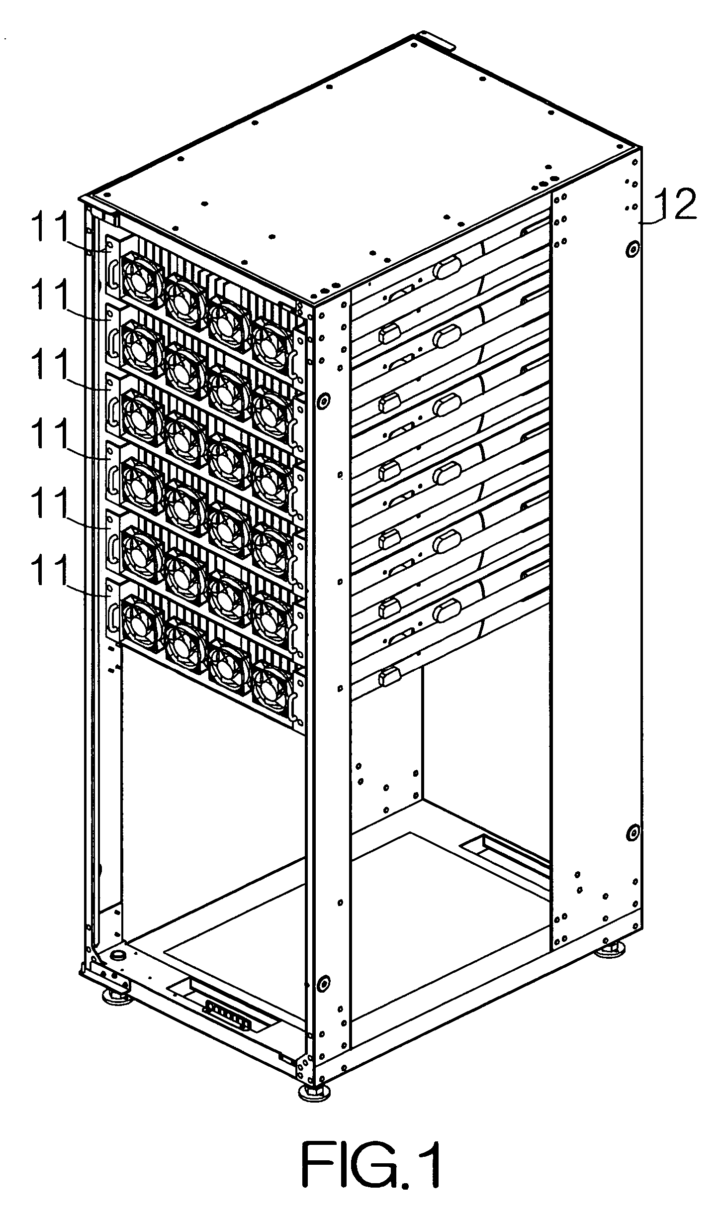
[0026]FIG. 1 schematically illustrates a rack 12 containing a rack mount type disk array apparatus 11 according to a specific embodiment of the present invention. The disk array apparatuses 11 are set in the rack 12. The disk array apparatuses 11 are connected to an upper host such as a server computer apparatus, not shown, likewise set in the rack 12. The disk array apparatuses 11 are allowed to operate based on instructions supplied from the server computer apparatus, for example.

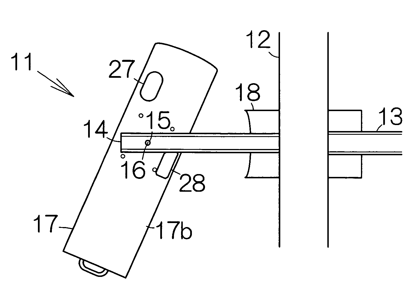
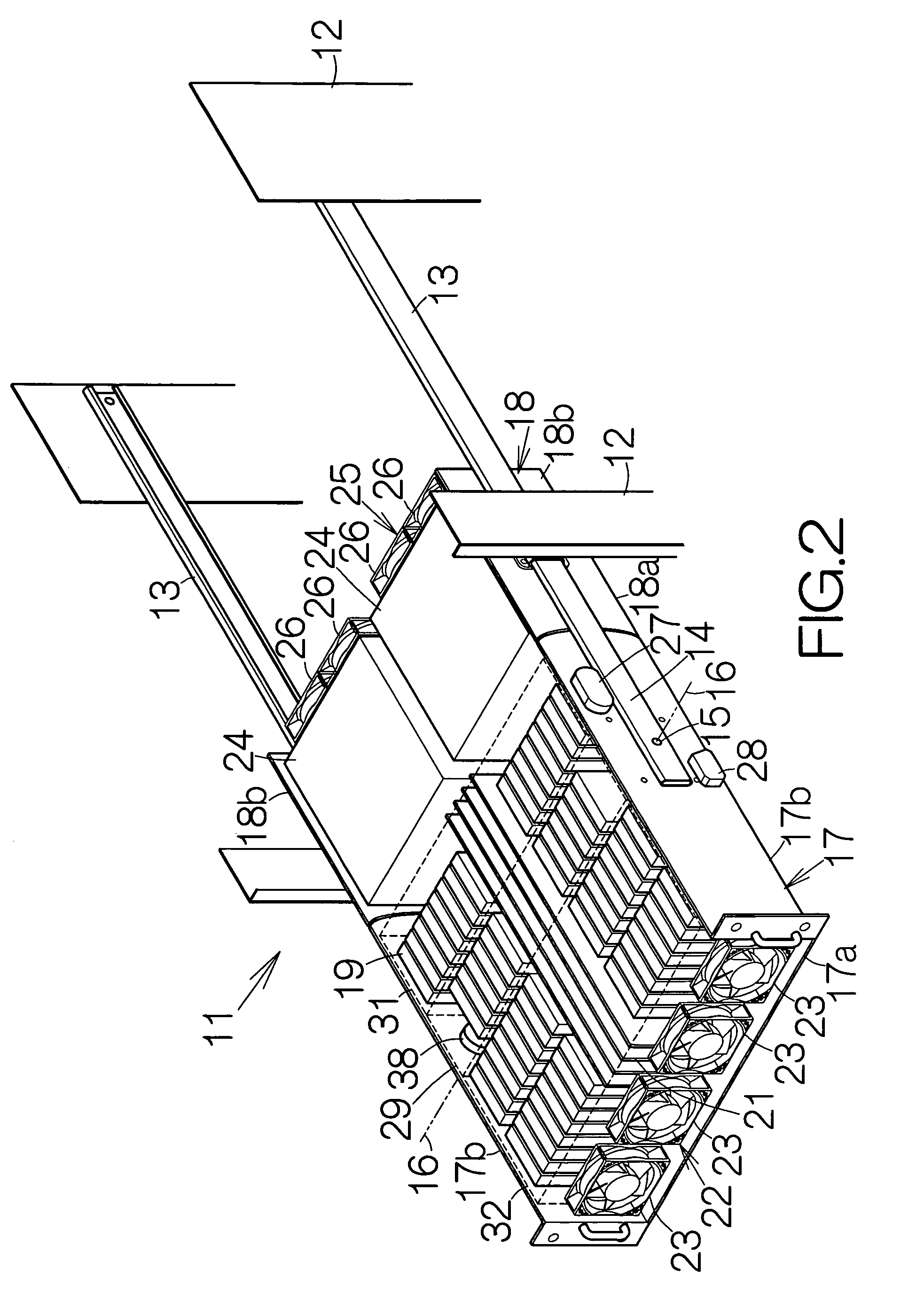
[0027]As shown in FIG. 2, a pair of guide member 13, 13 is fixed on the columns of the rack 12. The disk array apparatus 14 includes a pair of support member 14, 14. The support members 14, 14 are supported on the corresponding guide members 13, 13, respectively. The support member 14 is allowed to move in a longitudinal direction in the guide member 13. The guide members 13, 13 extend in parallel with each other. The support members 14, 14 thus extend in parallel with each other. The combination of the g...


PUM

PropertyMeasurementUnit
areaaaaaaaaaaa
weightaaaaaaaaaa
gravityaaaaaaaaaa

Abstract

A support member is designed to move in the longitudinal direction in a rack mount type disk array apparatus. A frame member is attached to the support member for relative rotation around the rotation axis located between the front and rear ends of the frame member in the longitudinal direction. Recording disk drives are held within the frame member in an upright attitude. The recording disk drives can be removed from and inserted into the frame member in a facilitated manner. This leads to a facilitated replacement of the recording disk drives. Moreover, the upper face of the frame member is allowed to face forward through the rotation around the rotation axis. Even if the disk array apparatus is placed at a higher level, the operator easily accesses the recording disk drives in the frame member.

Description

BACKGROUND OF THE INVENTION[0001]1. Field of the Invention[0002]The present invention relates to a rack mount type storage unit. In particular, the invention relates to a rack mount type storage unit applicable to a rack mount type disk array apparatus.[0003]2. Description of the Prior Art[0004]A rack mount type disk array apparatus is well known. Hard disk drives (HDDs) are held in rows in a frame member of the disk array apparatus. A row of the HDDs is mounted on a corresponding single printed circuit board. The HDDs are kept in an attitude parallel to the bottom plate of the frame member. The HDDs are arranged in a direction perpendicular to the bottom plate of the frame member. When the HDD is replaced with new one, the frame member is pulled out from a rack in the horizontal direction. The printed circuit board is then taken out from the frame member along with the HDD to be replaced. The HDD is pulled off from the printed circuit board. A new HDD is then mounted on the printed...

Claims


Application Information

Patent Timeline
Patent Type & Authority Patents(United States)
IPC IPC(8): G11B17/03
CPCG11B33/128G11B33/142
Inventor ISHIMINE, JUNICHISUZUKI, MASAHIRO
Owner FUJITSU LTD
Why Eureka
Try Eureka