Arrangement for cleaning surfaces with cleaning equipment having a cleaning belt

Active Publication Date: 2008-03-25
WANDRES MICRO CLEANING
View PDF22 Cites 6 Cited by
  • Summary
  • Abstract
  • Description
  • Claims
  • Application Information

AI Technical Summary

Benefits of technology

[0006]To attain this object, the arrangement according to the invention includes a presser device formed as at least one flexible cushion, and that the guide thereby acted upon is deflectable or bendable transversely of, or at right angles to the surface to be cleaned. The cleaning belt section is thereby pressed by means of the presser device against the wavy surface, whereby, due to the flexibility of the cushion or buffer, there occurs adaptation of the same together with the guide and the cleaning belt section to the contour of the surface to be cleaned. Together with the flexibility of the guide, the resilience of the cushion or buffer effects a substantially uniform pressing force on the surface located under the cleaning belt section, which in turn leads to the brushes or brush filaments contacting the surface to be cleaned only with their tips, so that an optimum cleaning result is obtained using brushes. The wiping elements to be used can however be of another kind, e.g. fibers or bonded fibers.
[0023]In order to obtain for the respective manipulation device or robot its complete freedom of movement and to accommodate no interfering objects in the region of the surface to be cleaned, the junction coupling is arranged near the drive motor for the linear brush and / or the drive motor for one of the reversing rollers or rolls and the cleaning device with its belt section extends away from the junction coupling. Thus actually only the cleaning device with its belt sections project away from the coupling into the region of the surface to be cleaned, while the drive motor is arranged near the coupling, which gives a favorable weight distribution. Thus the device can also find use on production robots with more complicated courses of movement,

Problems solved by technology

However, many surfaces to be cleaned have no planar geometry, but are for example curved, convex, or wavy.
In these heretofore known cleaning arrangements for surfaces, the problem exists that the device is brought near the respective surface at a given, predeterminable distance, and the cleaning process is then performed at this distance.
Already with regularly curved or wavy surfaces, in particular also with a geometry which changes over the surface, there can thus be unsatisfactory cleaning results, since firstly the bristles or brush filaments at a given selected distance can be deformed such that they cover the wavy surface to be cleaned with a considerable portion of their length or else on the other hand do not contact the surface at all in a given region because of the changing distance.

Method used


Image

  • Arrangement for cleaning surfaces with cleaning equipment having a cleaning belt
  • Arrangement for cleaning surfaces with cleaning equipment having a cleaning belt
  • Arrangement for cleaning surfaces with cleaning equipment having a cleaning belt

Examples


Embodiment Construction

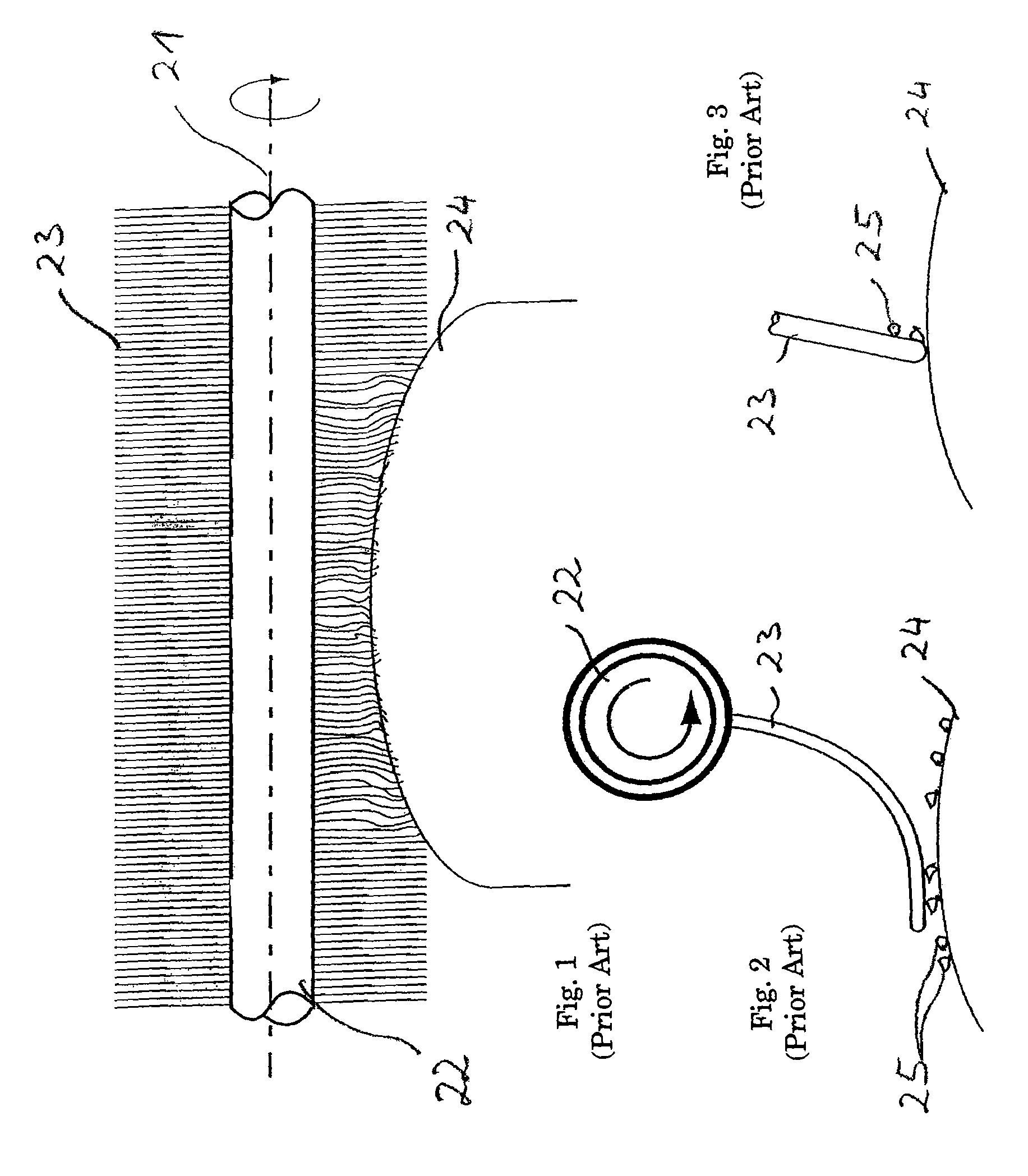
[0030]The arrangement shown in FIG. 1 can be used to explain the prior art device. Seen here is a brush roller 22 extending along an axis 21 and having bristles 23 extending radially from it and being rotated around the axis 21 in the direction of the arrow. This brush roller 22 is brought close, at a given distance, to the convex surface to be cleaned 24, so that the bristles 23 contact the surface 24. Based on the geometry of the surface 24, thus on its curvature in the direction toward the roller 22, the brushes 23 undergo a differently strong loading or curvature according to the place of the radius of curvature of the surface 24 where they are located.

[0031]Through examination of a single bristle 23, this can be gathered for the sake of example from FIG. 2, in which this is shown standing out substantially radially from the brush roller 22. The region of the free end of the bristle then covers a section of the portion of the surface shown here, which depends on the distance of ...


PUM


Abstract

An arrangement (1) for cleaning surfaces (2), particularly curved or arched or wavy surfaces and / or surfaces (2) with varying direction of curvature, for example on vehicle chassis, metal strip or unflat plates. The arrangement has a cleaning device (3) having a tension resistant carrier band or belt with an upper section and a lower section and also at least two reversing rollers or rolls (4), which device acts with a section as a cleaning belt section (6) on the surface to be cleaned (2) with its inner side facing the reversing rollers or rolls (4). The device (1) has a presser device (8) with a guide (9) for the cleaning belt section (6), through which the cleaning belt section (6) can be pressed. It is provided that the presser device (8) includes at least one flexible cushion or buffer (10), and that the guide (9) acted on thereby is deflectable or bendable transversely to, or at right angles to, the surface to be cleaned (2).

Description

BACKGROUND[0001]The invention relates to an arrangement for cleaning surfaces, particularly curved, arched or wavy surfaces and / or surfaces having a changing direction of curvature, for example, on vehicle chassis, metal strip, or unflat plates, with a cleaning device, having an upper section and a lower section and also at least two reversing rollers, which acts with one belt section as the cleaning belt section on the surface to be cleaned, and is fastened at its inner side facing the reversing rollers or rolls to a tension-resistant carrier band or belt, the device having a presser device with a guide for the cleaning belt section, by means of which the cleaning belt section can be pressed against the surface to be cleaned.[0002]Such an arrangement is known, for example from EP 0 813 914 B1, and has proved itself for the cleaning of flat surfaces. Such an arrangement is described in column 1, line 48 through column 2, line 6, as a cleaning device with a belt section as a cleaning...

Claims


Application Information

Patent Timeline
IPC IPC(8): B60S3/04B08B1/04A46B3/18B08B1/00B08B1/02
CPCA46B3/18B08B1/007B08B1/008B08B1/02B08B1/04B08B1/20B08B1/30B08B1/32B08B1/52B08B1/54B08B1/50
Inventor WEBER, MARTINWANDRES, CLAUS G.
Owner WANDRES MICRO CLEANING
Why Eureka
Try Eureka