Pre-mounting of a sensor

a sensor and pre-mounting technology, applied in the field of pre-mounting devices, to achieve the effect of easy pre-mounting and easy adjustmen

Inactive Publication Date: 2008-03-25
DR JOHANNES HEIDENHAIN GMBH
View PDF16 Cites 5 Cited by
  • Summary
  • Abstract
  • Description
  • Claims
  • Application Information

AI Technical Summary

Benefits of technology

[0005]It is an object of the invention to provide those skilled in the art with means for pre-mounting a structural part to be mounted to the attachment surface in an adjusted position, said means allowing easy pre-mounting and, in particular, easy adjustment.
[0009]The fine adjustment provided by the eccentrics allows a precision of positional adjustment clearly exceeding the precision with which the heads can be mounted to the attachment surface.
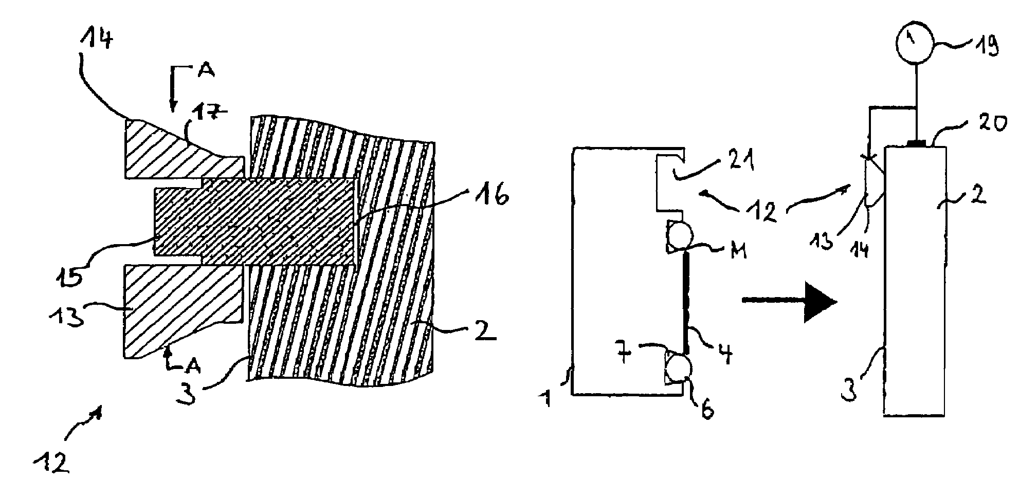
[0011]In principle, hanging-up of the structural part may be effected by means of said heads in almost any desired manner. Conveniently, a securing means will be additionally provided so as to prevent the structural part from falling off after being hung up. A possible measure for this purpose is a stepped structure on the heads in engagement with a corresponding back taper of the recess.
[0012]In a particularly advantageous further embodiment, such securing means against falling off may be provided such that it is effective for different distances between the structural part and the attachment surface. The eccentrics may then be used for differently dimensioned structural parts. A particularly simple measure for achieving this is a frustum portion on the heads which tapers toward the attachment surface.
[0015]It is particularly advantageous if the heads as well as the recess are designed such that, during final mounting, i.e. when the structural part is immovably secured to the attachment surface, a possible displacement of the structural part is effected by the counter-surface sliding on the cylindrical portion. This may allow such displacement to be a movement in only one direction. This direction may advantageously be selected such that it is irrelevant or at least non-critical for adjustment of the structural part. It is also possible to design this now exactly defined displacement as an aiming-off allowance or offset during adjustment, so as to achieve an exactly defined, desired adjustment position of the finally mounted structural part.
[0016]At least two heads are required to suspend the structural part. However, depending on the length of the structural part, a greater number of heads may also be used, which has the advantage that the requirements concerning the bending resistance of the structural part are reduced. In particular, it is convenient to provide a spacing between a plurality of heads such that said spacing between the heads prevents flexure of the suspended structural part beyond a certain acceptable measure.

Problems solved by technology

The final mounting by an adhesive bond as mentioned in the introduction of said document stringently requires the adjusted position to be set before initiating the adhesive bonding, because corrections are not possible after the adhesive bond has been realized.

Method used


Image

  • Pre-mounting of a sensor
  • Pre-mounting of a sensor
  • Pre-mounting of a sensor

Examples


Embodiment Construction

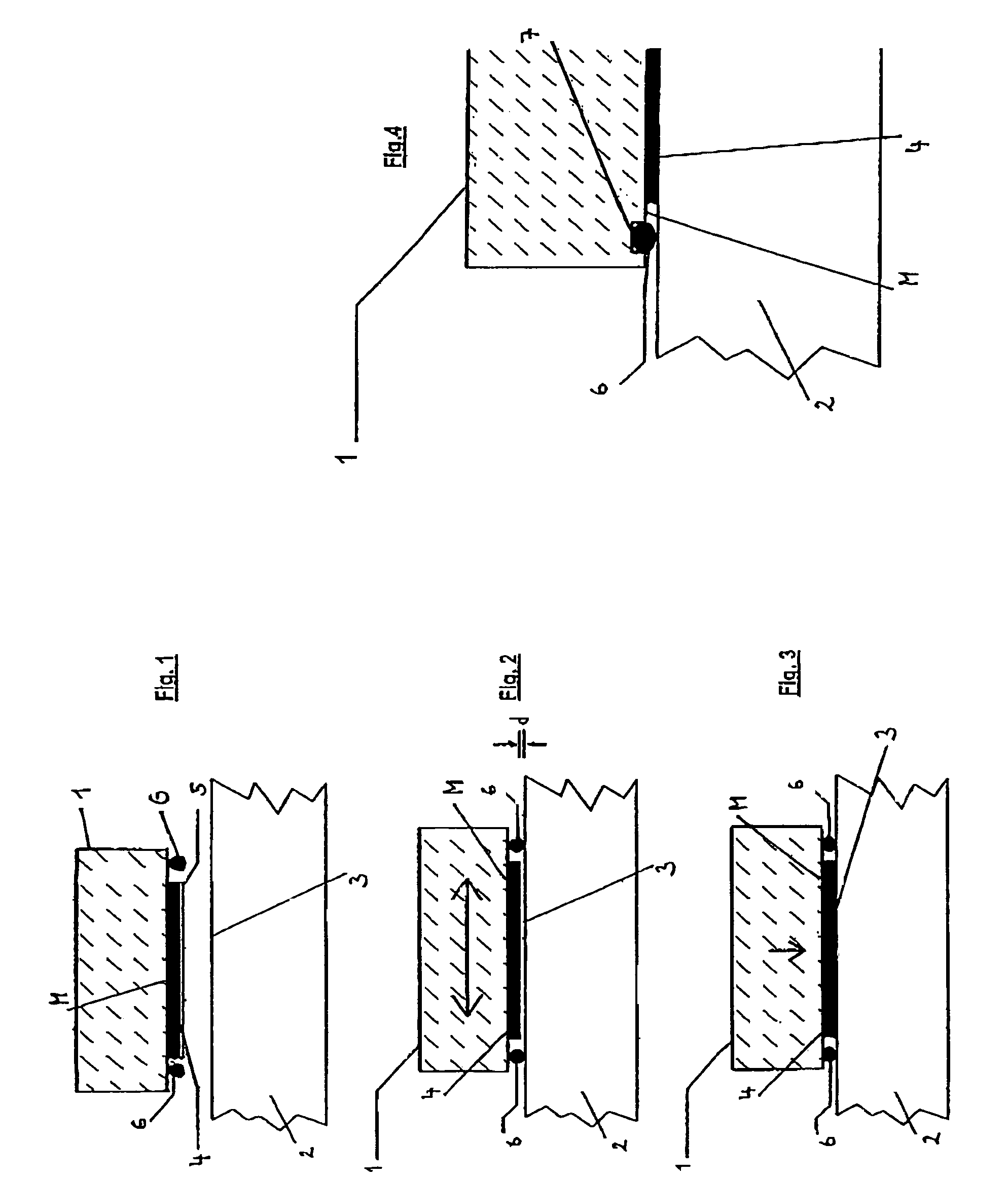
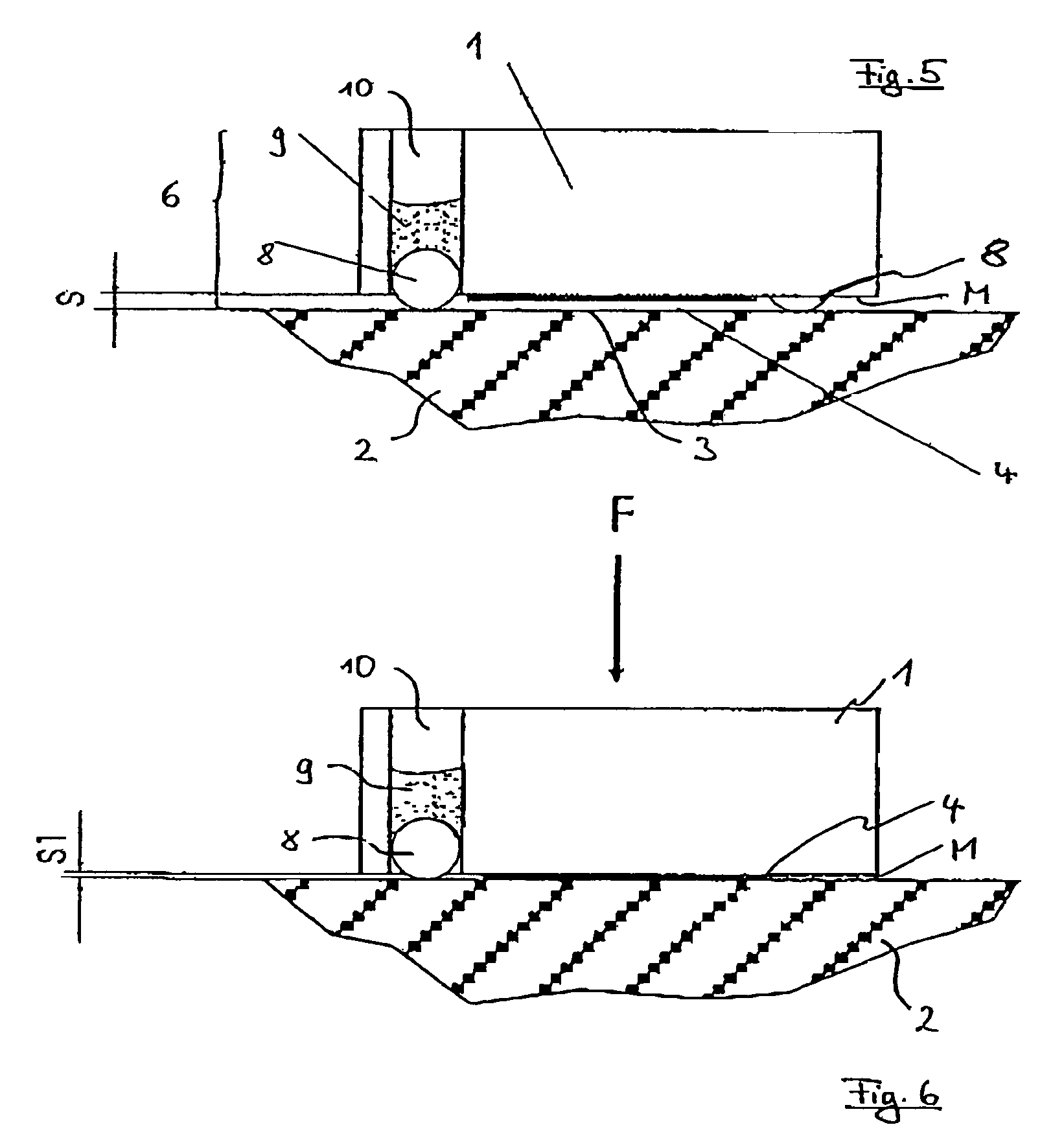
[0039]FIG. 1 shows a schematic sectional view of a sensor element 1, in a phase of the mounting process, before the sensor element 1 is mounted to a part 2. In the embodiment shown, the sensor element 1 is part of a measuring system (not shown in detail), which detects, for example, the movement of one machine part relative to another machine part. However, the sensor element may also be any other structural part which is to be mounted to an attachment surface or an attachment part in a determined position to be adjusted. It is merely essential for the following description that the element 1 be mounted to the part 2, e.g. to an attachment surface thereof, to achieve a position adjusted with high precision. The adjustment may relate to the part 2 or to a third part.

[0040]Mounting of the sensor element 1 to the part 2 is effected by connecting a mounting surface M of the sensor element 1 to the attachment surface 3, e.g. by means of an adhesive bond. For this purpose, an adhesive lay...


PUM


Abstract

What is described is a pre-mounting system for pre-mounting a structural part to an attachment surface, wherein at least two heads, respectively provided as eccentrics, are provided at the attachment surface, the structural part comprises at least one recess and can be hung up on the attachment surface by said heads engaging said recess / recesses.

Description

FIELD OF THE INVENTION[0001]The invention relates to a pre-mounting device for a structural part which is mountable in an adjusted position to an attachment surface. The invention further relates to a structural part which is pre-mounted by means of said pre-mounting element. Further, the invention relates to a pre-mounting system for pre-mounting a structural part to an attachment surface, as well as to a method of mounting a structural part to an attachment surface.BACKGROUND OF THE INVENTION[0002]In many cases, structural parts have to be mounted to attachment surfaces in predetermined positions. The predetermined position is usually set in an adjusting step and the structural part is then finally mounted to the attachment surface. The adjusted position should, of course, remain unchanged as far as possible. This problem is exemplified, for example, in length or angle measuring systems, in which a transducer element to be optically sensed has to be mounted to the corresponding ma...

Claims


Application Information

Patent Timeline
Patent Type & Authority Patents(United States)
IPC IPC(8): G01B5/24
CPCF16B5/0225F16B11/006G01D11/30
Inventor BOGE, LUDWIGFRANZ, HEINZ-GUNTHERFREITAG, HANS-JOACHIMSCHMIDT, ANDREAS
Owner DR JOHANNES HEIDENHAIN GMBH
Why Eureka
Try Eureka