Supercavitating projectile with propulsion and ventilation jet

a technology of ventilation jet and projectile, which is applied in the field of underwater projectiles, can solve the problems of speed and depth dependence of current projectiles, lack of propulsion of current projectiles,

Inactive Publication Date: 2008-03-25
THE UNITED STATES OF AMERICA AS REPRESENTED BY THE SECRETARY OF THE NAVY
View PDF16 Cites 27 Cited by
  • Summary
  • Abstract
  • Description
  • Claims
  • Application Information

AI Technical Summary

Benefits of technology

[0025]In operation, the propellant is combusted and the combusted gasses are forced forward through the forward-directed nozzle as a forward-directed jet to generate a virtual cavitator in the form of a ventilation gas bubble. Almost instantaneously combusted gasses are forced out rear-directed nozzle, forming a propulsion jet. Because of the larger volume of...

Problems solved by technology

Current projectiles lack propulsion in that the projectiles are instead launched from a gun at high speeds (of the order o...

Method used


Image

  • Supercavitating projectile with propulsion and ventilation jet
  • Supercavitating projectile with propulsion and ventilation jet
  • Supercavitating projectile with propulsion and ventilation jet

Examples


Embodiment Construction

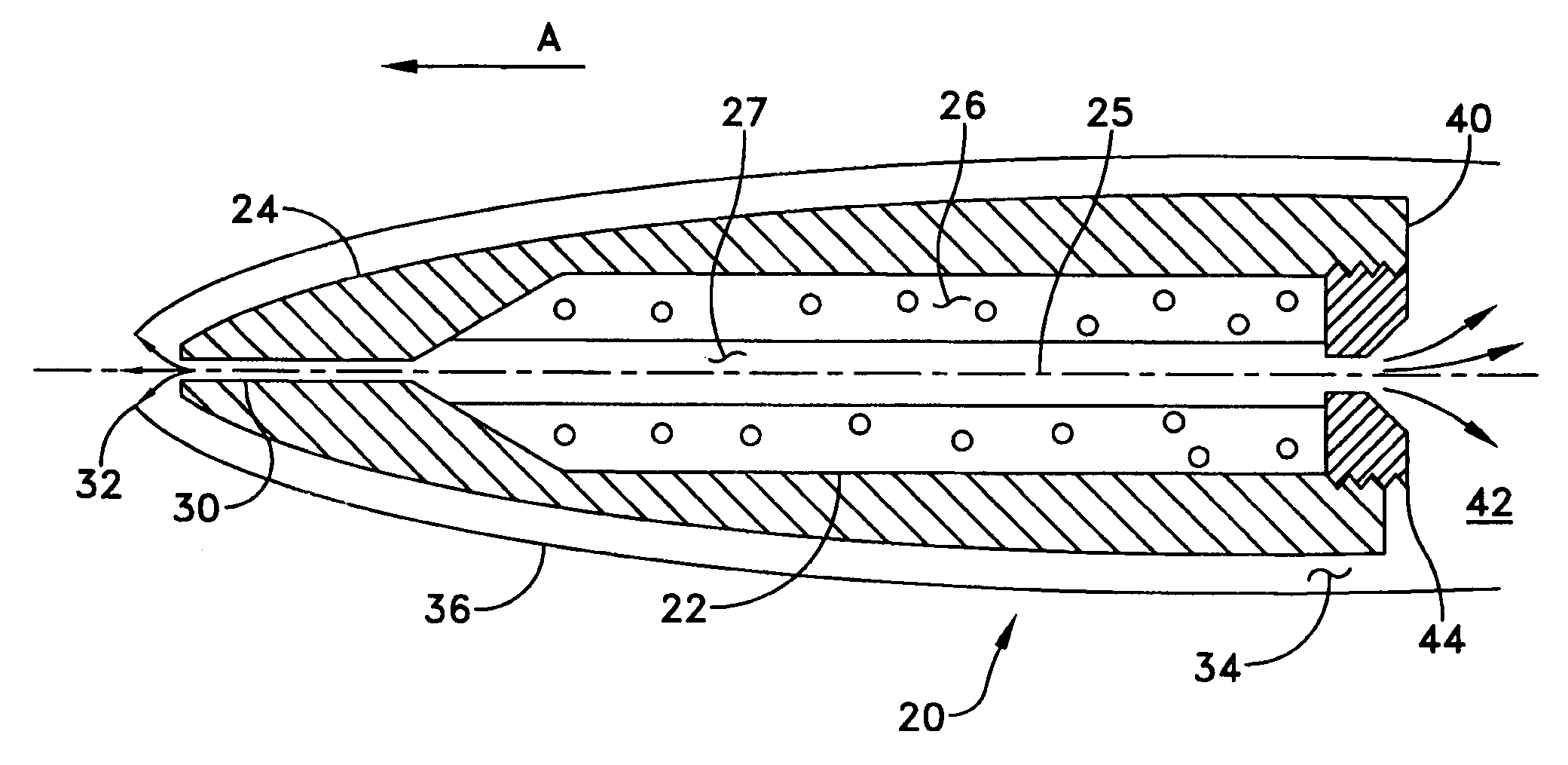
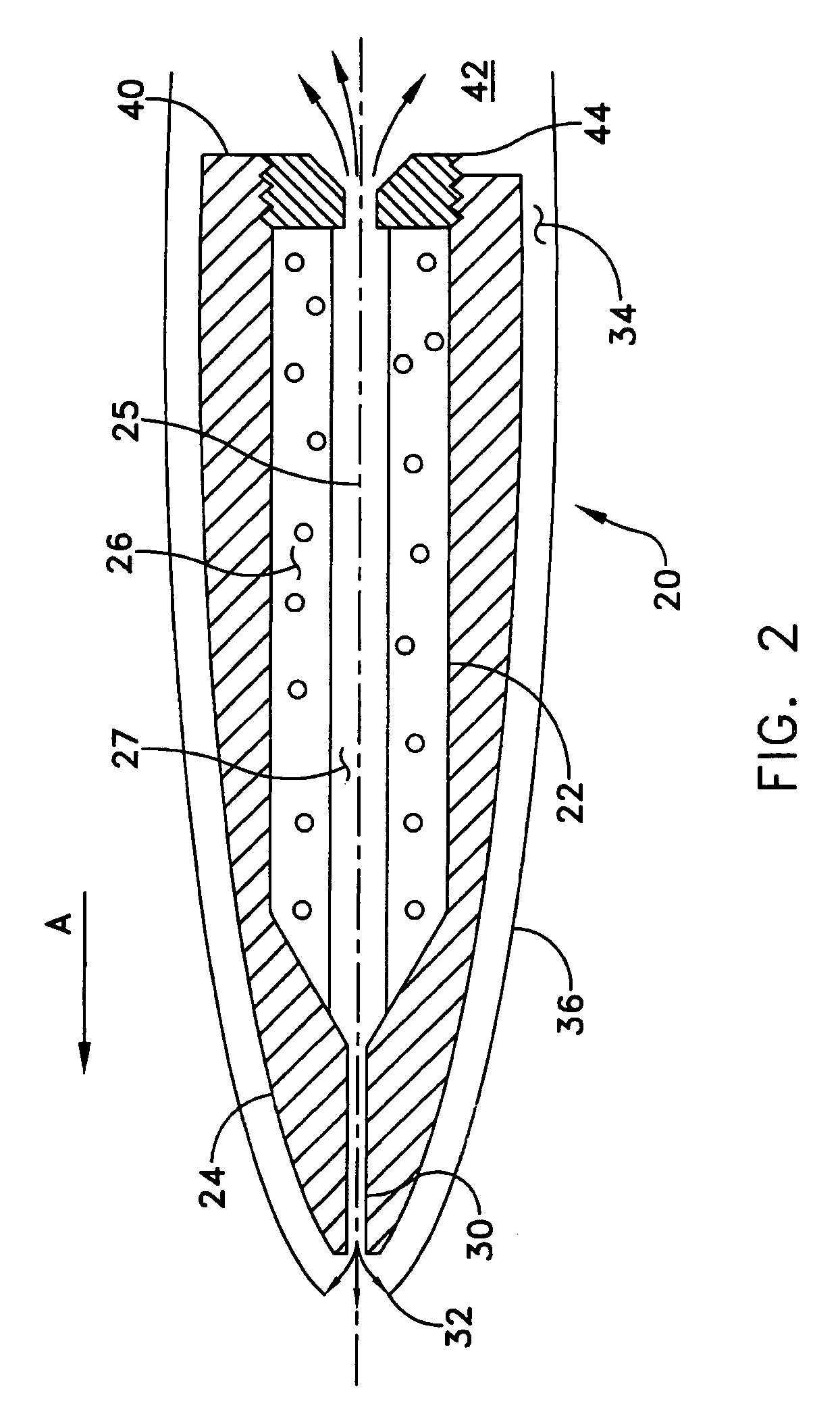
[0029]Referring now to FIG. 2, a supercavitating projectile 20 of the present invention is shown. The projectile 20 is capable of being launched by an underwater gun of a type known to those skilled in the art. The projectile 20 generally comprises a combustion chamber 22, a gas duct / forward-directed jet nozzle 30 and a comparatively larger gas duct / rear-directed jet nozzle 40.

[0030]The combustion chamber 22 is machined into a body 24 of the supercavitating projectile 20, preferably with an axis collinear to a longitudinal axis 25 of the projectile.

[0031]The combustion chamber 22 is filled with a solid propellant 26 having a hollowed core 27. The core 27 serves as a pathway to fluidly allow combustion gases to the jet nozzle 30 and the jet nozzle 40.

[0032]In operation, the propellant 26 is combusted and the combusted gasses are forced forward through the jet nozzle 30 as a forward-directed jet 32 to generate a virtual cavitator in the form of a ventilation gas bubble 34. This ventil...


PUM


Abstract

A supercavitating projectile is disclosed and includes a combustion chamber, a forward-directed jet nozzle and a comparatively larger gas duct/rear-directed jet nozzle. The combustion chamber is filled with a propellant having a hollowed core. The core serves as a pathway to fluidly allow combustion gases to the jet nozzles. In operation, the propellant combusts to form gasses forced forward through the forward-directed nozzle to generate a virtual cavitator in the form of a ventilation gas bubble. Combusted gasses are also forced out the rear-directed nozzle forming a propulsion jet. The projectile therefore uses the rear-directed jet to maintain a cruise velocity approximate to the launch velocity and employs a source of ventilation gas using the forward-directed jet for supercavitating of the projectile.

Description

STATEMENT OF GOVERNMENT INTEREST[0001]The invention described herein may be manufactured and used by or for the Government of the United States of America for governmental purposes without the payment of any royalties thereon or therefor.BACKGROUND OF THE INVENTION[0002](1) Field of the Invention[0003]The present invention relates to an underwater projectile that incorporates a ventilation gas jet emitting from a tip of the underwater projectile and a propellant gas jet emitting from a rear of the projectile. The gas jets are produced in a combustion chamber in which the forward-directed ventilation gas jet produces a virtual cavitator to form a gas bubble around the projectile body and the comparatively larger rear-directed propellant gas jet nozzle acts a propellant for the projectile and allows the gas bubble to act as a supercavitator by the moving direction of the projectile.[0004](2) Description of the Prior Art[0005]Presently, research is ongoing for the use of underwater gun...

Claims


Application Information

Patent Timeline
IPC IPC(8): F42B15/20F42B15/22
CPCF42B10/38F42B12/20F42B12/22
Inventor GIESEKE, THOMAS J.
Owner THE UNITED STATES OF AMERICA AS REPRESENTED BY THE SECRETARY OF THE NAVY
Why Eureka
Try Eureka