Apparatus for continuous blending

a technology of continuous blending and mixer, which is applied in the direction of mixing, transportation and packaging, rotary stirring mixer, etc., can solve the problems of material “hung up”, prior art continuous blenders are not very adaptable to different mixing requirements, and the output of continuous blenders is not adjustable, so as to prevent product leakage, rapid switch, and dramatic change

Active Publication Date: 2008-03-25
HEBELER PROCESS SOLUTIONS LLC
View PDF14 Cites 21 Cited by
  • Summary
  • Abstract
  • Description
  • Claims
  • Application Information

AI Technical Summary

Benefits of technology

[0013]These needs, and others, are met by the present invention which provides a continuous blender having a drive unit with a shell assembly mounting and a shell assembly structured to be removably coupled to the shell assembly mounting by one or more clamps. The drive unit may be coupled to shell assemblies having different lengths and diameters. Thus, by changing the shell assembly coupled to the drive unit, the output of the continuous blender may be dramatically changed.
[0014]The continuous blender also includes an intensifier with a separate drive motor. The shell assembly motor and the intensifier motor are independent of each other. Moreover, both the shell assembly motor and the intensifier motor may be run intermittently, at various speed, and in reverse. In this configuration, the mixing capabilities of the continuous blender are highly adjustable. The speed of the shell assembly motor and the intensifier motor, as well as an adjustable tilting mechanism, are controlled by a programmable control unit. The control unit may be programmed with various parameters associated with selected formulations. As such, the continuous blender may be quickly switched from one formulation to another. In addition, for a given formulation the controls allow for real time adjustment to maintain the formulation within acceptable limits. The system also utilizes Process Analytical Technology to provide a feedback loop.
[0015]The present invention also provides for a continuous blender wherein the zig-zag tube is cantilevered. That is, the zig-zag tube is not supported by trunnion rims. As such, there are fewer components subject to wear and tear. Additionally, the present invention provides for an air purged seal with a spherical surface between the drive unit and the shell assembly. Such an air purged seal with a spherical surface is useful in maintaining a controlled seal interface in preventing product leakage on a drive unit assembly with a cantilevered shell assembly.

Problems solved by technology

Of these factors, the size of the zig-zag tube had the greatest impact on the amount of material that could be blended and, as noted above, this was not adjustable.
As such, the prior art continuous blenders were not very adaptable to different mixing requirements.
The disadvantage of adding the intensifier was that the intensifier shaft housing was typically disposed in the path of the inlet chute and could cause the materials to become “hung up.” This was especially a problem where there was a very little amount of one material and any delay in introducing that material to the mix could cause uneven mixing.
Thus, even the improved continuous blender was not overly adaptable to different mixing routines.
Not only were these seals subject to wear and failure caused by normal use, but were also subject to additional wear on the trunnion rims and the casters.
In this condition, the wear on the trunnion rims and casters would create non-parallel sealing surfaces thereby creating gaps.
The gaps at the sealing surfaces allowed the product to leak.

Method used


Image

  • Apparatus for continuous blending
  • Apparatus for continuous blending
  • Apparatus for continuous blending

Examples


Embodiment Construction

[0028]As used herein, the phrase “removably coupled” means that one component is coupled with another component in an essentially temporary manner. That is, the two components are coupled in such a way that the joining or separation of the components is easy and would not damage the components. For example, two components secured to each other with a limited number of readily accessible fasteners are easily separated whereas two components that are welded together are not easily separated.

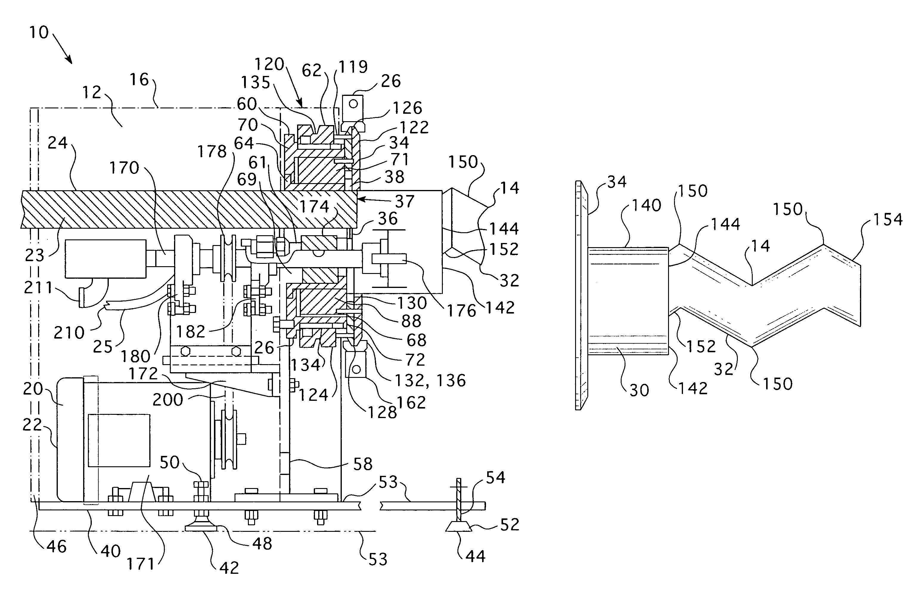
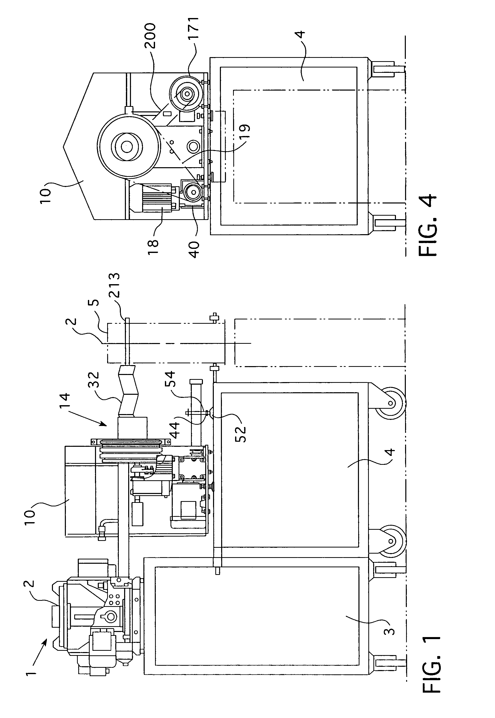
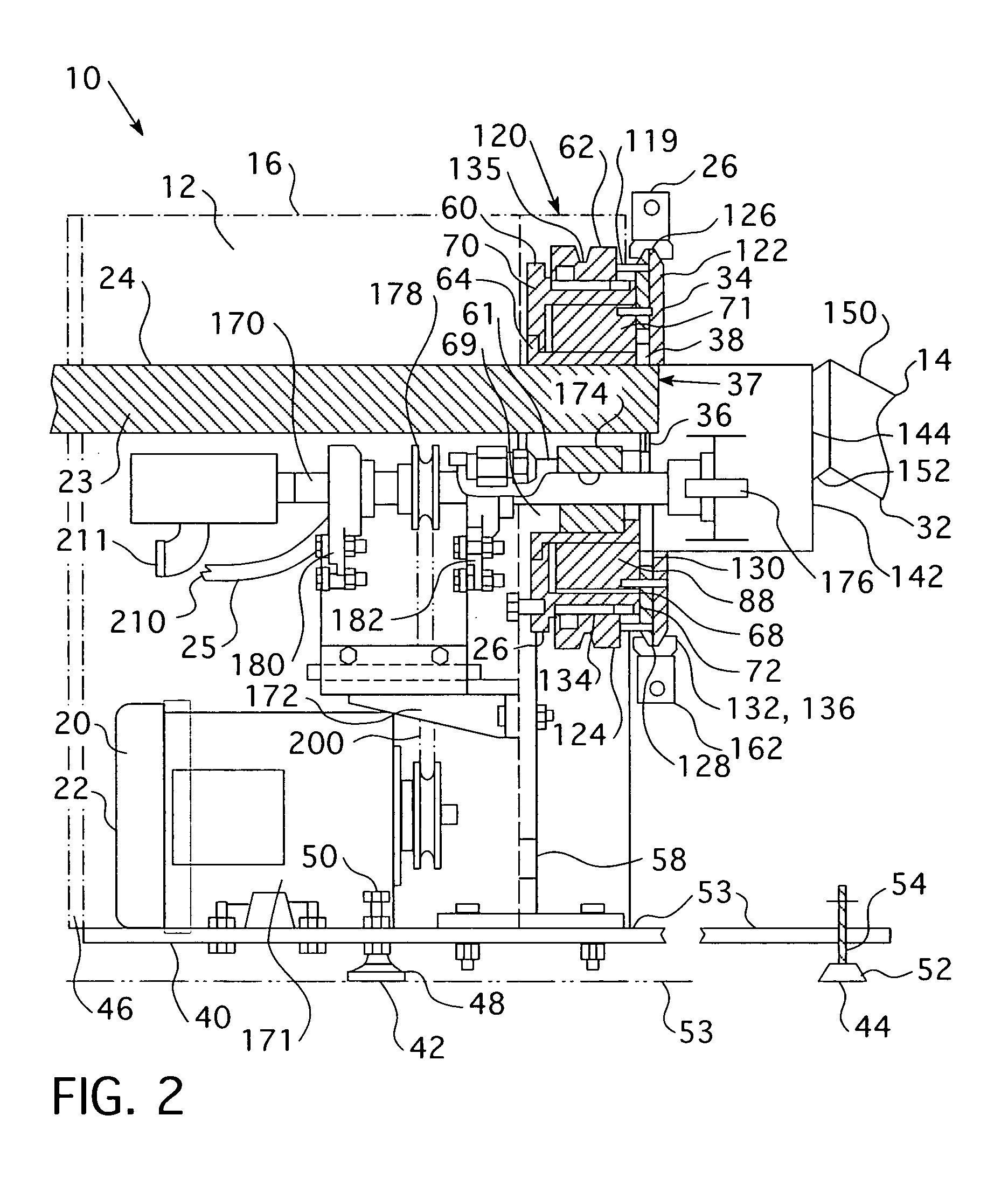
[0029]As shown in FIG. 1, a metered continuous blender 1 includes one or more metering devices 2, and a continuous blender 10. The components of the metered continuous blender 1 may be mounted on separate movable platforms 3, 4, thereby allowing the continuous blender 10 to be coupled to different metering devices 2. The metering devices 2 are structured to repeatedly eject a measured amount of a powdered material. The metering devices 2 are typically coupled to an input tube 24 (described below) o...


PUM


Abstract

The present invention provides a continuous blender having a drive unit assembly with a shell assembly mounting assembly and a shell assembly structured to be removably coupled to the shell assembly mounting assembly by one or more clamps. The drive unit assembly may be coupled to shell assemblies having different lengths and diameters. Thus, by changing the shell assembly coupled to the drive unit assembly, the output of the continuous blender may be dramatically changed.

Description

BACKGROUND OF THE INVENTION[0001]1. Field of the Invention[0002]This application relates to an apparatus for continuous blending and, more specifically, to a continuous blender that is adaptable to produce different output rates.[0003]2. Background Information[0004]Continuous blenders are known in the prior art, see e.g. U.S. Pat. No. 3,341,182. Such blenders included an inlet chute, an initial mixing chamber and a zig-zag mixing tube with an outlet. The inlet chute had an opening into the mixing chamber. The mixing chamber had an outlet to the mixing tube. Generally, two or more, preferably dry, materials were introduced into the continuous blender via the inlet chute. The mixing chamber and the mixing tube were then rotated in order to mix the materials. The zig-zag tube was made from a series of V-shaped and inverted V-shaped sections. Thus, when the lateral axis of the zig-zag tube was in a vertical plane, the zig-zag tube had a series of peaks and valleys, with each vertex of a...

Claims


Application Information

Patent Timeline
Patent Type & Authority Patents(United States)
IPC IPC(8): B01F9/08B01F29/64
CPCB01F9/0009B01F9/0036B01F9/005B01F9/08B01F15/0235B01F2009/0089B01F29/251B01F29/40118B01F29/4011B01F29/4021B01F29/64B01F35/71731
Inventor DITZIG, JOSEPHCHIRKOT, THOMASLY, KIET C.
Owner HEBELER PROCESS SOLUTIONS LLC
Why Eureka
Try Eureka