Microtitration plate

a microtitration plate and plate body technology, applied in the field of microtitration plates, can solve the problems of unsuitable pcr or oxygen supply, and achieve the effects of improving the wall thickness, not impairing the dimensional stability of the microtitration plate any longer, and low tolerances

Inactive Publication Date: 2008-03-25
EPPENDORF AG
View PDF33 Cites 31 Cited by
  • Summary
  • Abstract
  • Description
  • Claims
  • Application Information

AI Technical Summary

Benefits of technology

[0015]Because of its stiffness, the frame of the microtitration plate is particularly suited for being handled by automatic devices. Preferably, its edge is provided with a bordering protruding from the underside which increases its stability, may form a surface to stand on and a surface for engagement by the automatic device. For this purpose, the frame may be manufactured so as to have particularly low distortion and particularly low tolerance. The first plastic may be an amorphous plastic or even a partially crystalline, heavily filled plastic. The plastic concerned may be polycarbonate which actually is unsuited for the PCR or oxygen supply. Since this plastic is confined to the frame, however, it allows to utilize its advantageous characteristics even for microtitration plates for the PCR or oxygen supply to samples.
[0019]Since the frame is manufactured from a first plastic and the vessels are manufactured from a second plastic the best solutions possible will be achieved with materials which correspond to the desired functions of the frame and vessels. Higher rigidity, better planarity, a lower tendency to distortion, and smaller tolerances are achieved by using an amorphous, rigid, and highly temperature-resistant material for the frame. The extremely thinness of the walls for better heat transfer is achieved by molding the vessels thereto in a direct way. The frame is not filled via the vessels so that the entire pressure gradient always is available to one vessel only. The vessels may be molded of soft materials suited for the PCR. It is uncritical to mold the frame. It preferably may have several edge-side gate marks (about four to six) provided on the frame edge.
[0022]For manufacture at particularly low tolerances, it is preferred to mold the frame initially and the vessels subsequently. This has the advantage that the frame first may undergo a certain shrinkage before the vessels are molded thereto. The time interval from molding the frame to molding the vessels thereto may be chosen so that the shrinkage of the frame (by cooling it down) essentially is effected completely. Once the vessels are molded on, shrinking techniques virtually do not impair the dimensional stability of the microtitration plate any longer. It specifically is the tolerance of the vessel-to-vessel distance which, thus, can be confined to very low values (about t 0.15 mm). This makes it easier to introduce proportioning needles with no wall contact.
[0023]It is particularly advantageous here if the upper wall region of the vessels is designed as a collar of an increased wall thickness because the collar may compensate hole position tolerances that have remained during molding.
[0030]In this microtitration plate, the at least one integrated sealing, in conjunction with a rigid lid, makes possible rapid and simple sealing of the apertures which satisfies the high requirements to tightness. It is particularly advantageous for handling and sealing that the lid is designed so as to be adapted to be locked with the frame, specifically by locking it with the marginal area of the frame. Specifically if designed with a plane seal at its underside, the lid can also be used with known microtitration plates having thermoplastic sealing collars at the apertures of the vessels.

Problems solved by technology

The plastic concerned may be polycarbonate which actually is unsuited for the PCR or oxygen supply.

Method used


Image

  • Microtitration plate
  • Microtitration plate
  • Microtitration plate

Examples


Embodiment Construction

[0041]In the drawings, the same elements are designated by identical reference numerals. The description pertaining thereto applies to all of the embodiments.

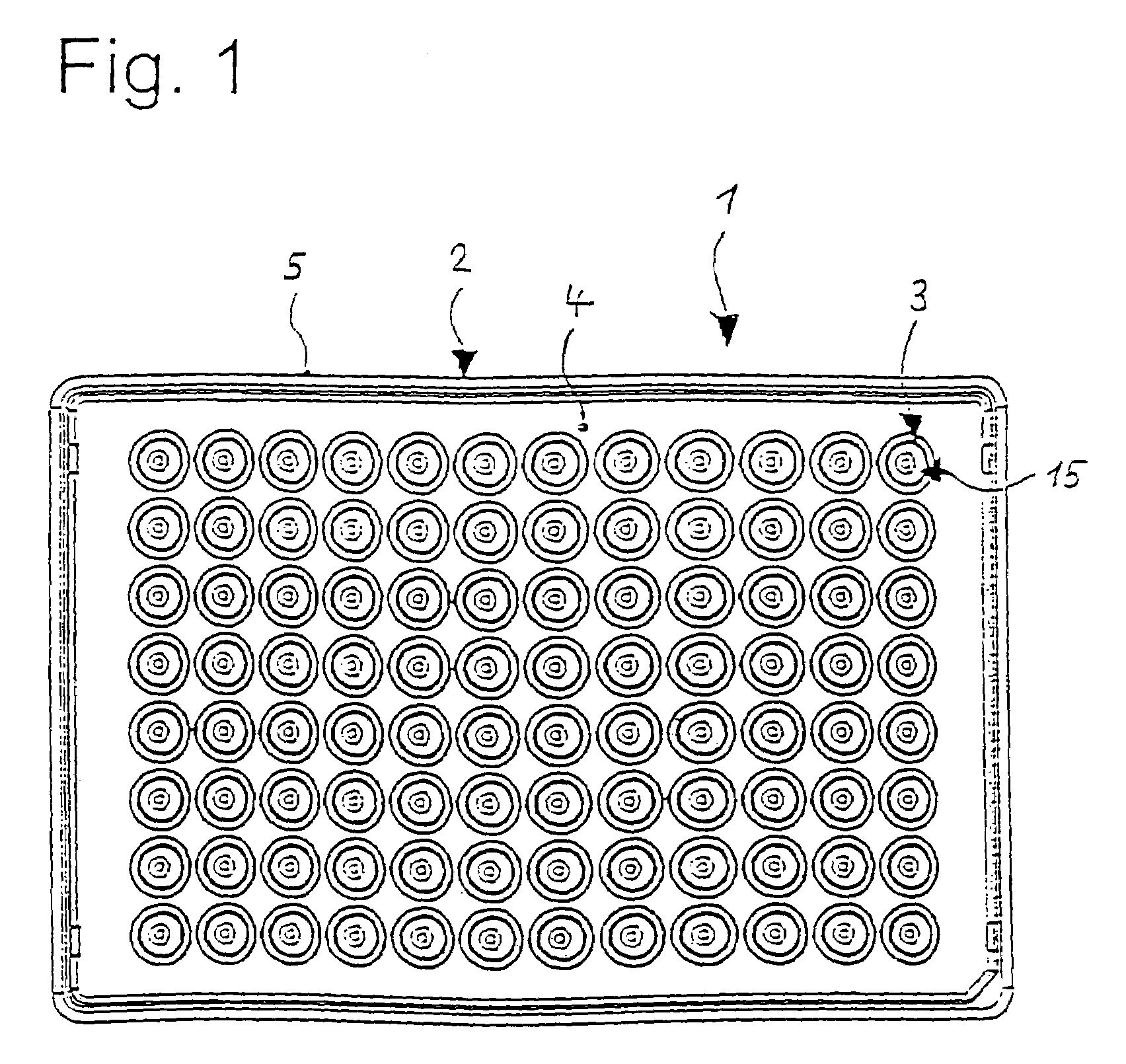
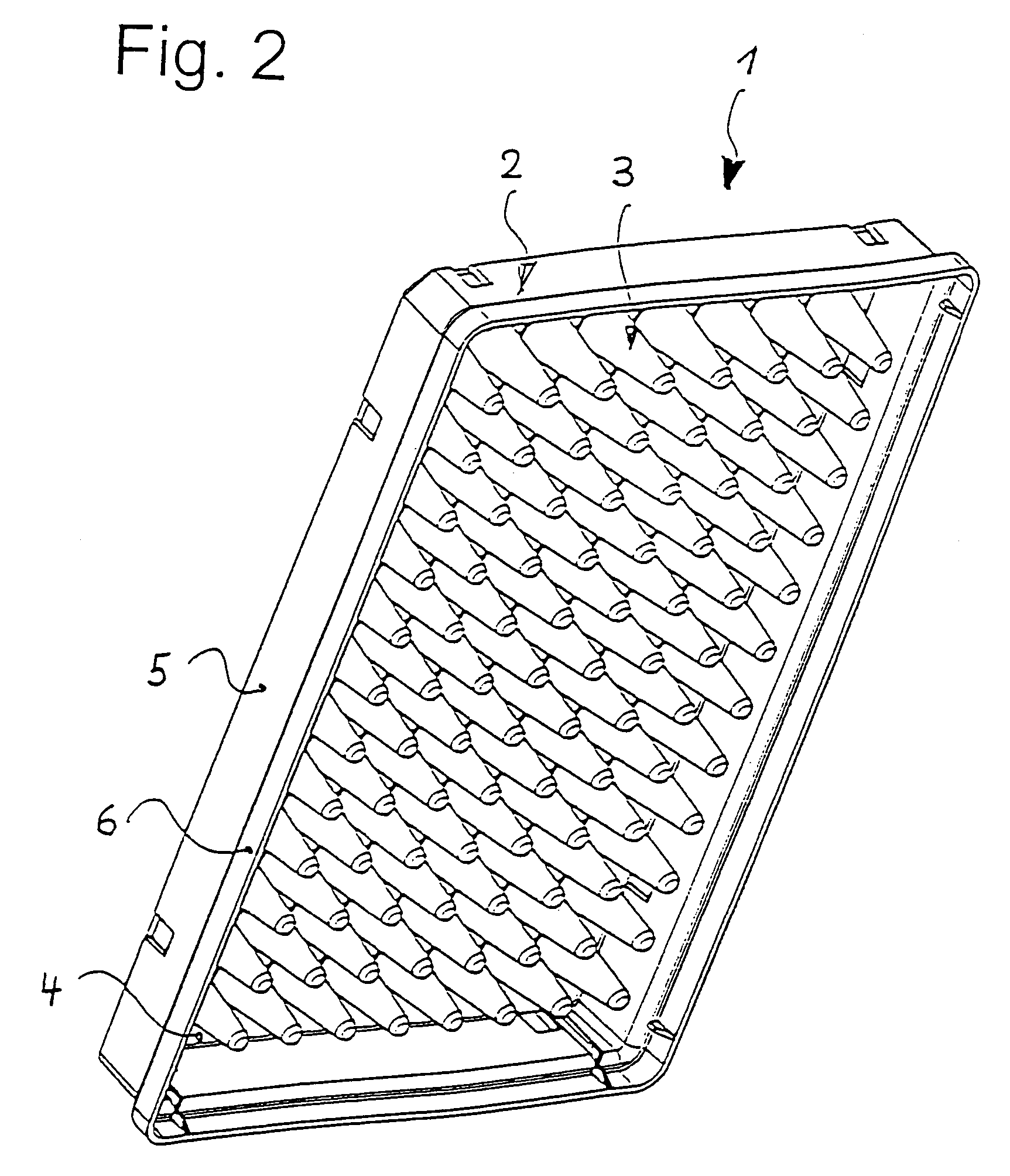
[0042]Referring to FIGS. 1 through 3, a microtitration plate 1 comprises a frame 2 and a multiplicity of vessels 3. There is a total of 96 vessels arranged in eight columns and twelve rows.

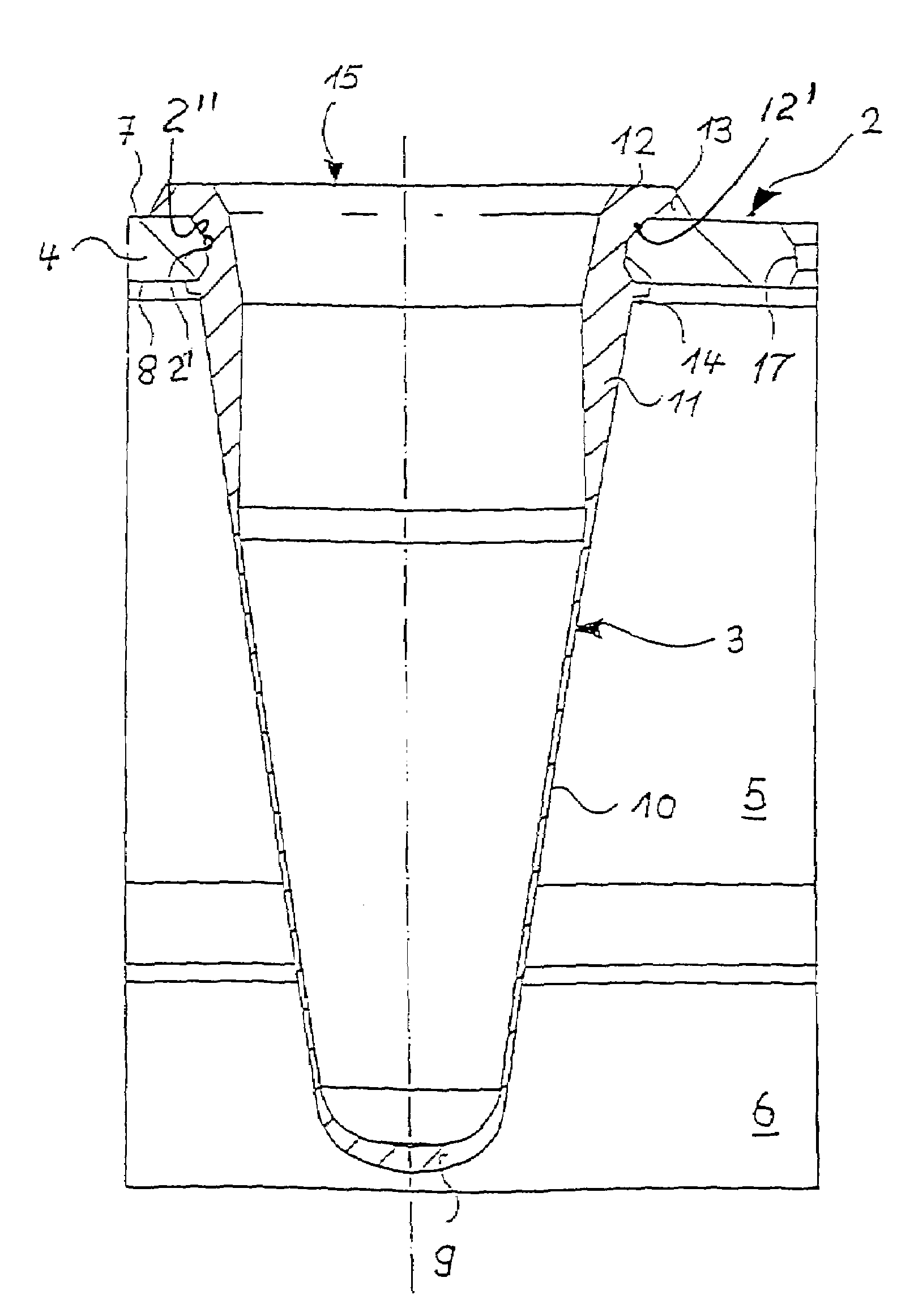
[0043]The frame 2 has a substantially rectangular plate 4 the outer edge of which is surrounded by a bordering 5 which protrudes approximately perpendicular from the underside of the plate 4, i.e. beyond the vessels 3. At bottom, the bordering 5, as is known, has an expansion 6 which enables stacking on the upper surface of an appropriate microtitration plate 1.

[0044]The frame 2 has a total of ninety-six holes 2′ in the plate 4. These have a profile 2″ of the cross-section which widens towards the upper surface 7 of the plate 4 in two portions of different conicity and towards the underside 8 of the plate 4 in a conical portion.

[0045]In a fir...


PUM


Abstract

A microtitration plate has a frame (2) made of a first stiff plastic and having a plate (4) with multiplicity of holes (2′), and a multiplicity of vessels (3) made of a second plastic suited for the PCR and / or exhibiting permeability to oxygen, which are fixedly connected to the plate (4) by directly molding them to the holes (6), which have a receiving portion (9, 10, 11) protruding from an underside (8) of the plate (4), and which are accessible from an upper surface (7) of the plate through apertures (15).

Description

RELATED APPLICATIONS[0001]This application is a continuation-in-part of application Ser. No. 09 / 867,087 filed May 29, 2001 now abandoned.BACKGROUND OF THE INVENTION[0002]The present invention relates to a microtitration plate.[0003]Microtitration plates are used for most varied microbiological, cell-breeding, and immunological techniques. In particular, microtitration plates are employed for the PCR (polymerase-chain-reaction) or the breeding of microorganisms or cells.[0004]Microtitration plates have already been known which have a frame with a plate to which a multiplicity of vessels are fixed which have a receiving portion protruding from the underside of the plate and are accessible from the upper surface of the plate through apertures. The vessels are also referred to as “wells”. The current 96-type microtitration plates have 8×12=96 vessels in rows and columns. However, microtitration plates having a larger number of vessels are used more and more.[0005]Single-component microt...

Claims


Application Information

Patent Timeline
Patent Type & Authority Patents(United States)
IPC IPC(8): B01L3/00
CPCB01L3/5085B01L3/50851B29C45/14344B29C45/16B01L3/50853B01L2200/12B01L2300/0829C12M23/12
Inventor GUELZOW, NICOPETERSEN, BERND OHM
Owner EPPENDORF AG
Why Eureka
Try Eureka