
Communications system of two-wire line enhancing fail-safe performance

a technology of fail-safe performance and communication system, applied in the field of communication system, can solve the problems of limiting the communication speed to a low value and not solving the foregoing problem

Inactive Publication Date: 2008-03-25
DENSO CORP
View PDF13 Cites 21 Cited by
  • Summary
  • Abstract
  • Description
  • Claims
  • Application Information

AI Technical Summary

Benefits of technology

[0011]It is an object of the present invention to enhance fail-safe performance for a break failure of a two-wire communications line in a communications system that is required to have terminating resistors connected to both ends. A plurality of communications devices conduct communication via the two-wire communications system.
[0013]A standby resistor that can be a terminating resistor is provided to correspond to all or a part of the communications devices. Further, when a break failure occurs in the two-wire communications line, a failed point of the two-wire communications line is located and the standby resistor corresponding to a given communications device arranged near the failed point is connected as the terminating resistor to the two-wire communications line. The part of the communications devices including the given communications device and the communications devices arranged opposite to the failed point when viewed from the given communications device are enabled to conduct communication. Even if the break failure occurs at any point in the two-wire communications line, the foregoing part of the communications devices can conduct communication in the same manner as under normal operating conditions. Thus, this can improve fail-safe performance for the break failure in the two-wire communications line.
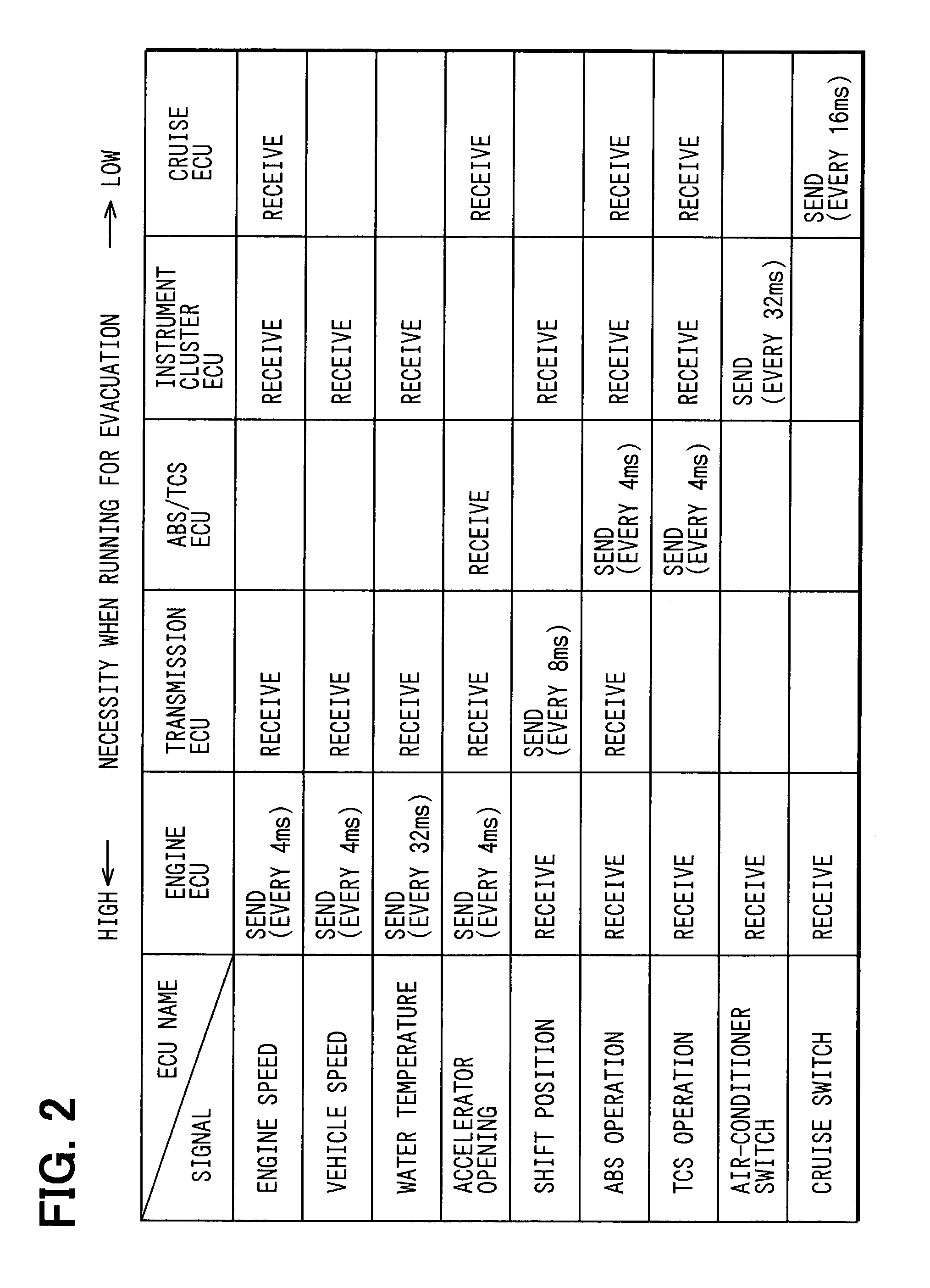
[0017]This is because in a case where the two-wire communications line is broken, this can reduce the possibility that the broken point becomes a point where it is impossible to make the devices essential to running for evacuation conduct the communication at the high speed. In other words, this can raise the possibility that it is possible to make the communications devices essential to running for evacuation conduct the communication at the high speed.

Problems solved by technology

In this case, however, each ECU 101 uses only one of the H line 11 and the L line 12 and thus is susceptible to noises, fluctuations in signal level, and the like, whereby the communication speed is limited to a low value.
However, this technique disclosed in this publication of patent application can not produce a fail-safe effect in a case where a break failure occurs in the CAN bus and hence can not solve the foregoing problem.

Method used


Image

  • Communications system of two-wire line enhancing fail-safe performance
  • Communications system of two-wire line enhancing fail-safe performance
  • Communications system of two-wire line enhancing fail-safe performance

Examples


Embodiment Construction

[0026]An embodiment to which the present invention is applied will be hereinafter described by the use of the drawings.

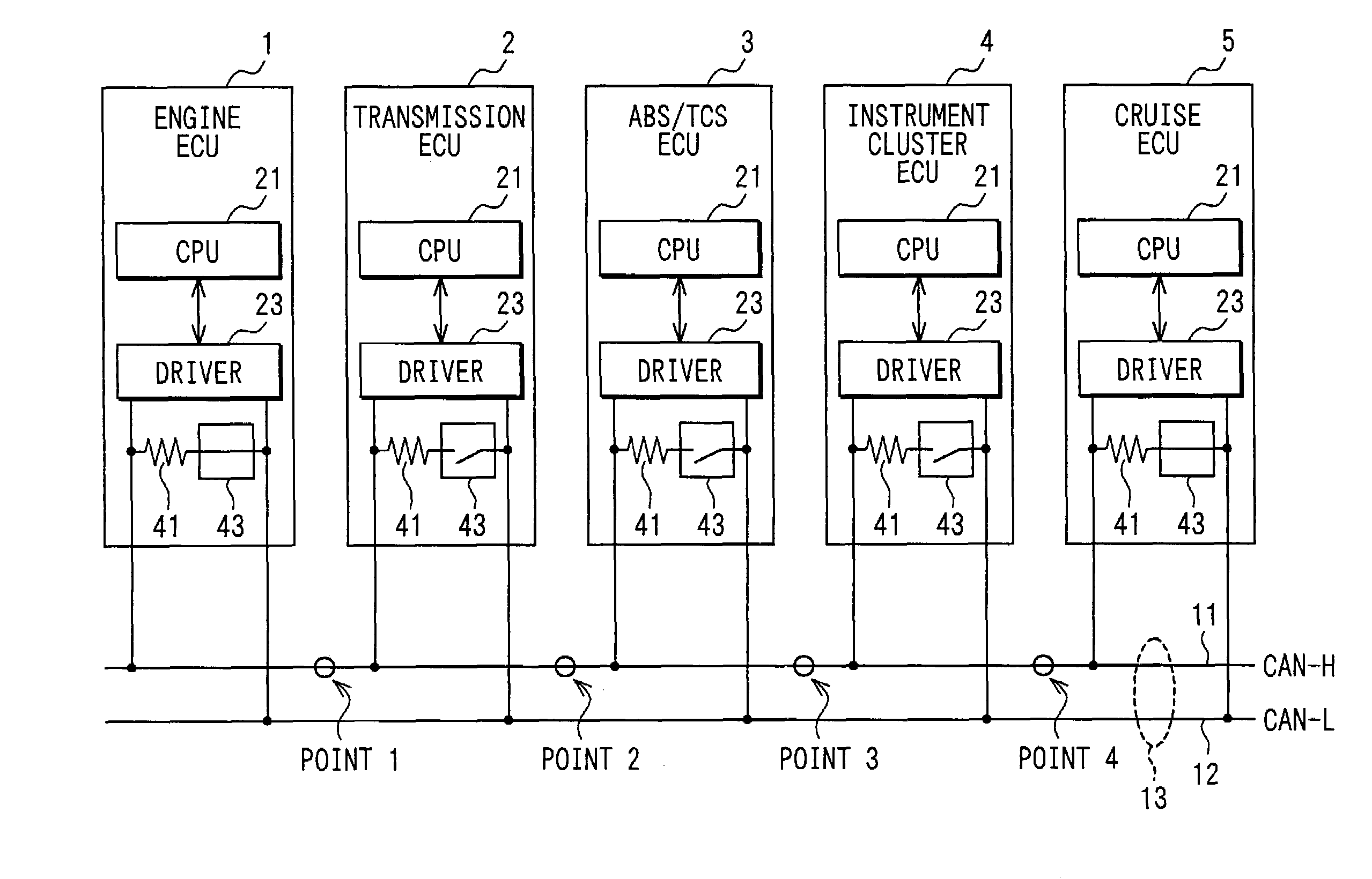
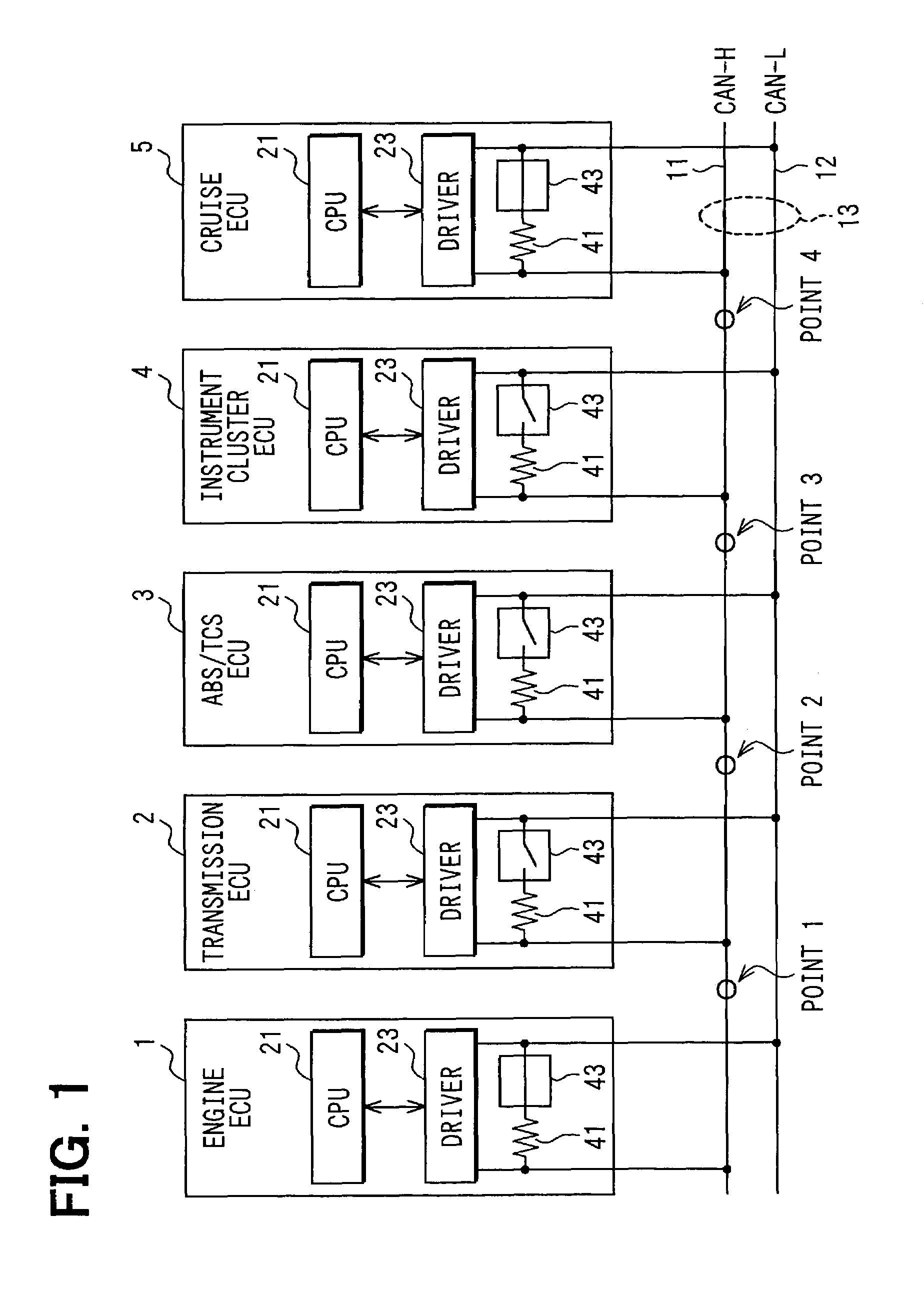
[0027]First, FIG. 1 is a configurational diagram showing a communications system of the embodiment. Here, the same constituent elements shown in FIG. 1 as shown in FIG. 7 are denoted by the same reference symbols and their detailed descriptions will be omitted. Moreover, in the following description, expressions relating to a left-right direction such as left end and right end means the left-right direction in FIG. 1

[0028]As shown in FIG. 1, in the communications system of the present embodiment, a plurality of (five, in the present embodiment) ECUs (electronic control unit corresponding to communications device) 1 to 5 are for controlling the respective parts of an automobile. The ECUs 1 to 5 conduct data communication with each other in accordance with a CAN protocol to control objects which are allotted to the respective ECUs and are to be controlled.

[0029]Here, ...


PUM


Abstract

Five electronic control units (ECU) control vehicle devices using CAN protocol. Each of ECUs is provided with a resistor and a switch for activating the resistor. A first and fifth ECUs are arranged on the leftmost and rightmost ends. Resistors of the first and fifth ECUs are used as terminating resistors to a two-wire communications line. When the two-wire communications line is broken, the first ECU sends a test signal while other ECUs excluding the fifth ECU turn on the switches from right to left. When the test signal can be received, a broken point is located on the right side of ECU that turns on its switch at this time. Thereafter ECUs on the left side of the broken point conduct communication.

Description

CROSS REFERENCE TO RELATED APPLICATIONS[0001]This application is based on and incorporates herein by reference Japanese Patent Application No. 2002-107792 filed on Apr. 10, 2002.FIELD OF THE INVENTION[0002]The present invention relates to a communications system in which a plurality of communications devices conduct communication via a two-wire communications line having terminating resistors connected to both ends thereof. In particular, the communications system is provided with a fail-safe performance.BACKGROUND OF THE INVENTION[0003]A CAN (Controller Area Network) has been conventionally used, for example, as a communication protocol of a LAN (local area network) in an automobile.[0004]Here, an outline of the CAN will be described by the use of FIG. 7. In this respect, in FIG. 7 and the following description based on FIG. 7, it is assumed that each communications device conducting communication in accordance with the CAN protocol is one of a plurality of (=n) electronic control ...

Claims


Application Information

Patent Timeline
IPC IPC(8): H04B3/00H04L25/00H04L12/40B60R16/023H04L69/40
CPCH04L69/40
Inventor SUGANUMA, TAKESHIFUJII, YOSHIMITSU
Owner DENSO CORP
Learn More