Optical transmission system for radio access and high frequency optical transmitter

a transmission system and optical transmitter technology, applied in electromagnetic transmission, multiplex communication, electrical equipment, etc., can solve the problems of n expensive devices, high-frequency devices are generally expensive, and the level of electric signals is reduced, so as to avoid the distortion avoid the decrease of the level of the electric signal, and low cost

Inactive Publication Date: 2008-03-25
PANASONIC CORP
View PDF10 Cites 29 Cited by
  • Summary
  • Abstract
  • Description
  • Claims
  • Application Information

AI Technical Summary

Benefits of technology

[0035]According to the first aspect, with respect to a downstream system, the electrical-optical converter can be thus shared, and the external modulator for performing optical frequency conversion can be shared because no electrical frequency converter is required. Further, the signals can be multiplexed more easily, thereby making it possible to more easily increase the transmission capacity with the increasing number of subscriber terminals, as compared with the conventional optical transmission system.
[0147]In such a configuration, it is possible to easily make a delay adjustment for canceling the light frequency modulation component by integrating the phase modulator for canceling the light frequency modulation component and the intensity modulator for performing frequency conversion. Further, the electric signal inputted to the phase modulator and the local oscillation signal inputted to the intensity modulator need not be multiplexed, thereby making it possible to further reduce the power of the electric signal inputted to the intensity modulator.

Problems solved by technology

The first problem is that the electrical-optical converters 611 to 61n, whose number (=n) corresponds to the number of the radio base stations 701 to 70n, are required in the center station 600.
The second problem is that the expensive frequency converters 731 to 73n for frequency-converting the IF signals into the RF signals are respectively required in the plurality of radio base stations 701 to 70n.
The third problem is that when information to be transmitted to a lot of subscriber terminals are transmitted upon being time-division multiplexed, a multiplexer is required in the center station 600.
Such high-frequency devices are generally expensive.
In such a configuration that the center station 600 manages the plurality of radio base stations 701 to 70n as in the other conventional optical transmission system, therefore, n expensive devices are required, so that the entire system becomes very expensive.

Method used


Image

  • Optical transmission system for radio access and high frequency optical transmitter
  • Optical transmission system for radio access and high frequency optical transmitter
  • Optical transmission system for radio access and high frequency optical transmitter

Examples


first embodiment

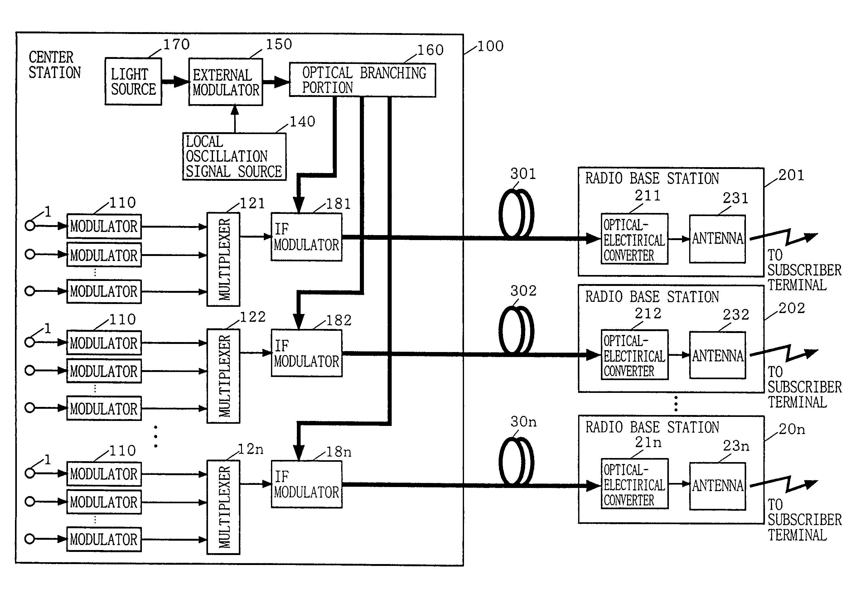
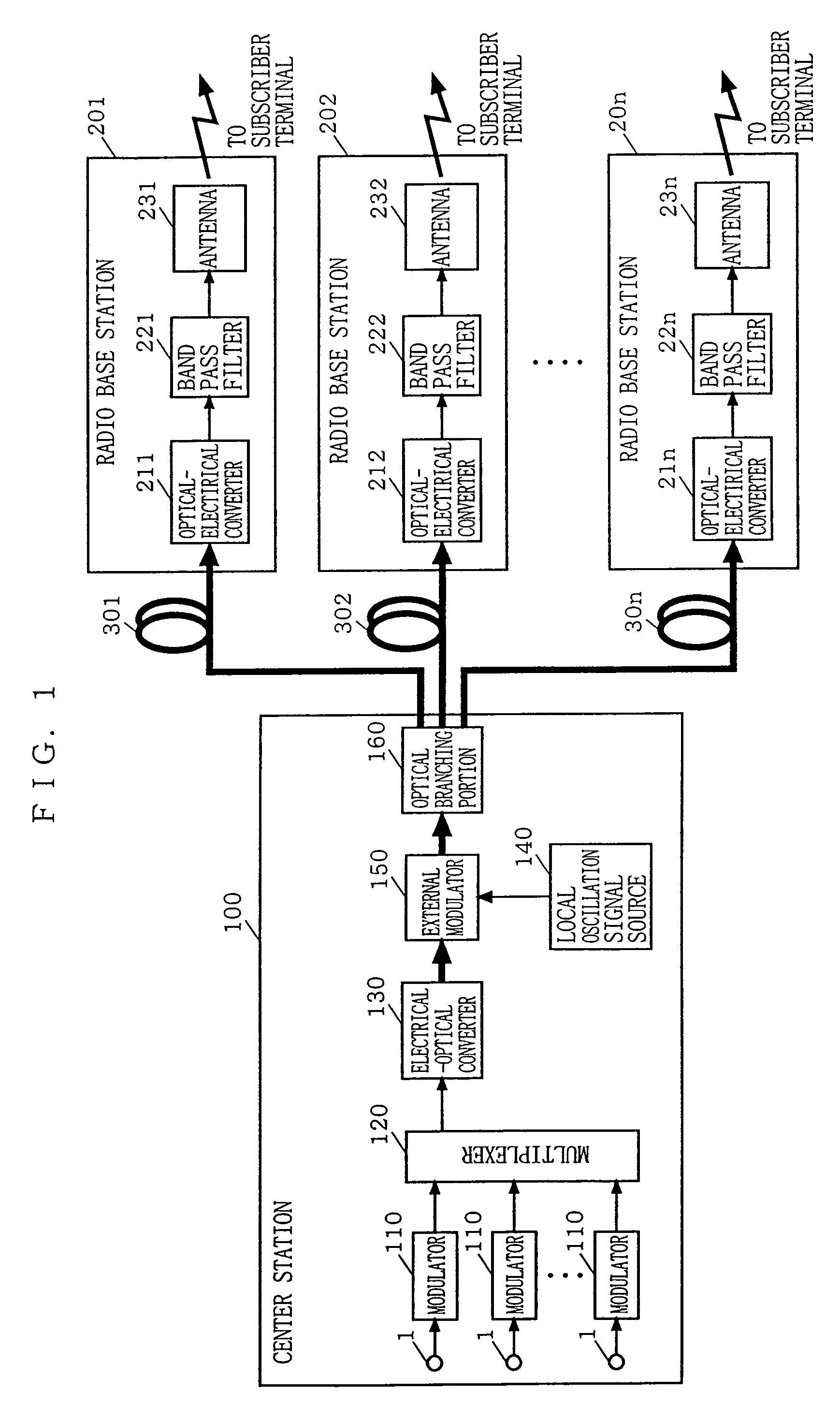
[0168]FIG. 1 is a block diagram showing the configuration of an optical transmission system for radio access according to a first embodiment of the present invention. In FIG. 1, the optical transmission system according to the first embodiment is so constructed that a center station 100 and a plurality of radio base stations 201 to 20n are respectively connected to each other through a plurality of downstream optical fibers 301 to 30n.

[0169]The center station 100 includes a plurality of modulators 110, a multiplexer 120, an electrical-optical converter 130, a local oscillation signal source 140, an external modulator 150, and an optical branching portion 160. The radio base stations 201 to 20n respectively include optical-electrical converters 211 to 21n, band filters 221 to 22n, and antennas 231 to 23n. The operation of the optical transmission system according to the first embodiment will be described.

[0170]In the center station 100, different information to be transmitted to sub...

second embodiment

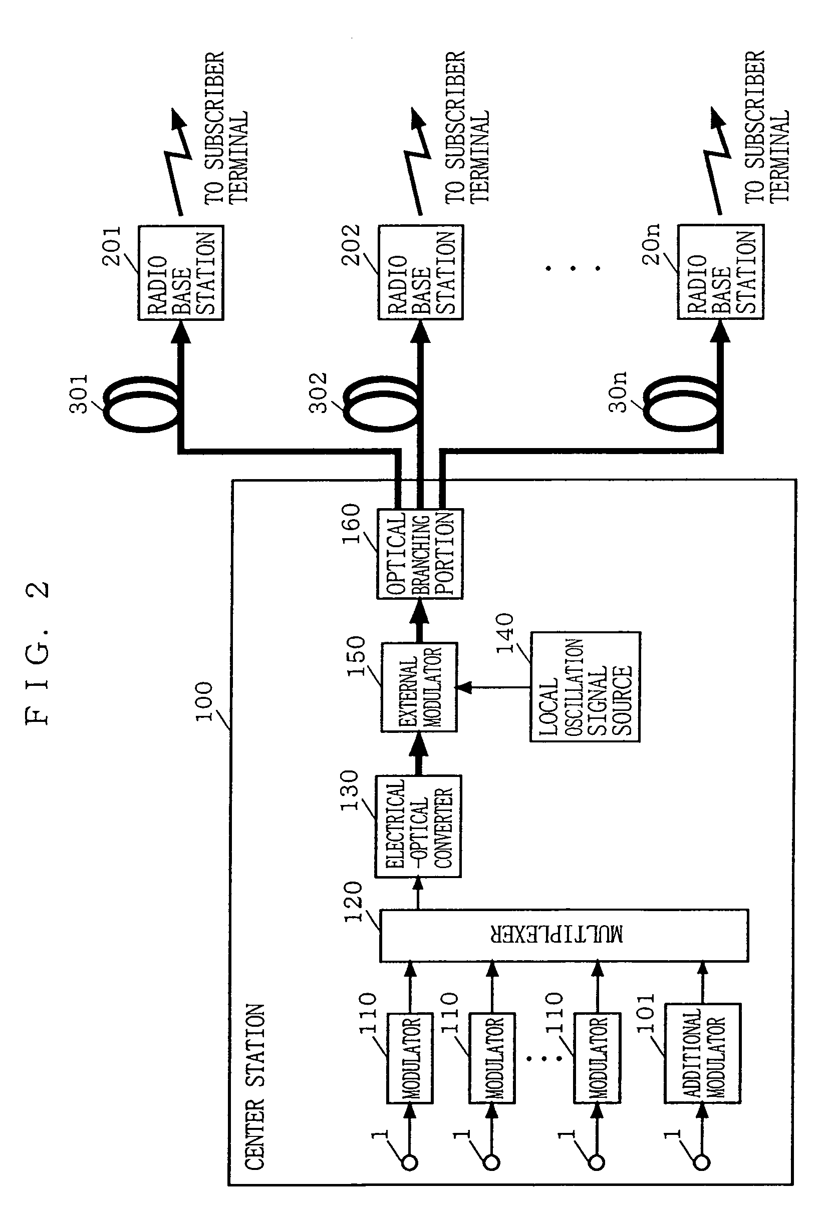
[0182]In the optical transmission system according to the first embodiment, the plurality of IF signals are multiplexed by the frequency division multiplexing, and the IF signals frequency-division multiplexed are doubly intensity-modulated. In the radio base stations 201 to 20n, therefore, the band filters 221 to 22n must be respectively used to extract RF signal components having desired radio frequencies from the transmitted RF signals.

[0183]In the second embodiment, description is made of an optical transmission system which does not respectively require the band filters 221 to 22n in the configurations of radio base stations 201 to 20n.

[0184]FIG. 3 is a block diagram showing the configuration of an optical transmission system for radio access according to a second embodiment of the present invention. In FIG. 3, the optical transmission system according to the second embodiment is so constructed that a center station 100 and a plurality of radio base stations 201 to 20n are res...

third embodiment

[0189]The first and second embodiments were characterized by a case where information is transmitted from the center station to the subscriber terminal (in a downstream direction). Accordingly, description was made of the optical transmission system comprising the configuration for only downstream transmission.

[0190]In the third embodiment, description is then made of an optical transmission system in which an RF signal in an optical signal state obtained by frequency-converting an IF signal is utilized for a case where information is transmitted from a subscriber terminal to a center station 100 (in an upstream direction), to simplify a configuration required for upstream transmission.

[0191]FIG. 4 is a block diagram showing the configuration of an optical transmission system for radio access according to a third embodiment of the present invention. In FIG. 4, the optical transmission system according to the third embodiment is so constructed that a center station 100 and a pluralit...


PUM


Abstract

Modulators respectively modulate baseband signals into IF signals having different frequencies. Multiplexers multiplex the IF signals. A local oscillation signal source outputs a predetermined local oscillation signal. An external modulator intensity-modulates an optical signal using the local oscillation signal. An optical branching portion branches the intensity-modulated optical signal. Modulators respectively modulate the multiplexed IF signals onto the branched optical signals and then output the optical signals to radio base stations. Optical-electrical converters convert the optical signals into electric signals and antennas transmit the electrical signals to subscriber terminals.

Description

[0001]This application is a divisional application of Ser. No. 09 / 892,605, filed Jun. 28, 2001 now abandoned.BACKGROUND OF THE INVENTION[0002]1. Field of the Invention[0003]The present invention relates generally to an optical transmission system for radio access and a high frequency optical transmitter, and more particularly, to an optical transmission system for connecting, in radio access for coupling a center station and a plurality of subscriber terminals with a radio signal (a high frequency radio signal in a microwave band, a millimeter wave band, or the like), the center station and a radio base station by an optical fiber, and a high frequency optical transmitter used for the system.[0004]2. Description of the Background Art[0005]FIG. 17 illustrates an example of the configuration of a conventional optical transmission system used for radio access for connecting a center station and a subscriber terminal through a radio base station for transmitting and receiving a radio si...

Claims


Application Information

Patent Timeline
Patent Type & Authority Patents(United States)
IPC IPC(8): H04B10/00H04J14/00H04B10/12
CPCH04B10/25753H04B10/25754
Inventor SASAI, HIROYUKIFUSE, MASARU
Owner PANASONIC CORP
Why Eureka
Try Eureka