Eureka AIR delivers breakthrough ideas for toughest innovation challenges, trusted by R&D personnel around the world.

Method and a device for monitoring a state of a blood line in a machine for extracorporeal blood treatment

a blood line and extracorporeal technology, applied in the direction of fluid leakage detection, fluid tightness measurement, instruments, etc., can solve the problems of deterioration of blood, not completely preventing the risk of damage to some components of the circuit, and requiring a sophisticated and expensive control device, etc., to achieve reliable and precise, simple structure, reliable and compact in size

Active Publication Date: 2013-02-21
GAMBRO LUNDIA AB
View PDF1 Cites 3 Cited by
  • Summary
  • Abstract
  • Description
  • Claims
  • Application Information

AI Technical Summary

Benefits of technology

The present invention relates to a method and device for monitoring the state of a blood line in a machine for extracorporeal blood treatment. The technical effects of this invention include: early detection of partial or total stenoses in the blood line, high safety level against damage to the components of the blood line and against deterioration of the blood passing through the line, reliable and precise monitoring of blood line state, simple operation, economical device design, and compact size.

Problems solved by technology

This method therefore does not entirely prevent the risk of damage to some components of the circuit, or deterioration of the blood (hemolysis) in the case of stenosis, as the reaction time of the control device can in some cases be not sufficiently rapid, also because there can sometimes be sufficient pressure variations for brief periods of time to damage the blood or some components.
The method however requires a sophisticated and expensive control device, which is able to perform complex calculation, such as frequency analysis of a signal in real time.
Both the above-described methods further require the presence of a high number of pressure sensors in the extracorporeal blood treatment circuit, in order to detect the changes in pressures in the various parts of the circuit, with a consequent increase in the complexity and costs of the system.
Further, these methods essentially allow only verification of stenoses in the blood line, while not enabling detection of further significant parameters relating to the functioning state of the extracorporeal blood circuit.

Method used


Image

  • Method and a device for monitoring a state of a blood line in a machine for extracorporeal blood treatment
  • Method and a device for monitoring a state of a blood line in a machine for extracorporeal blood treatment
  • Method and a device for monitoring a state of a blood line in a machine for extracorporeal blood treatment

Examples


first embodiment

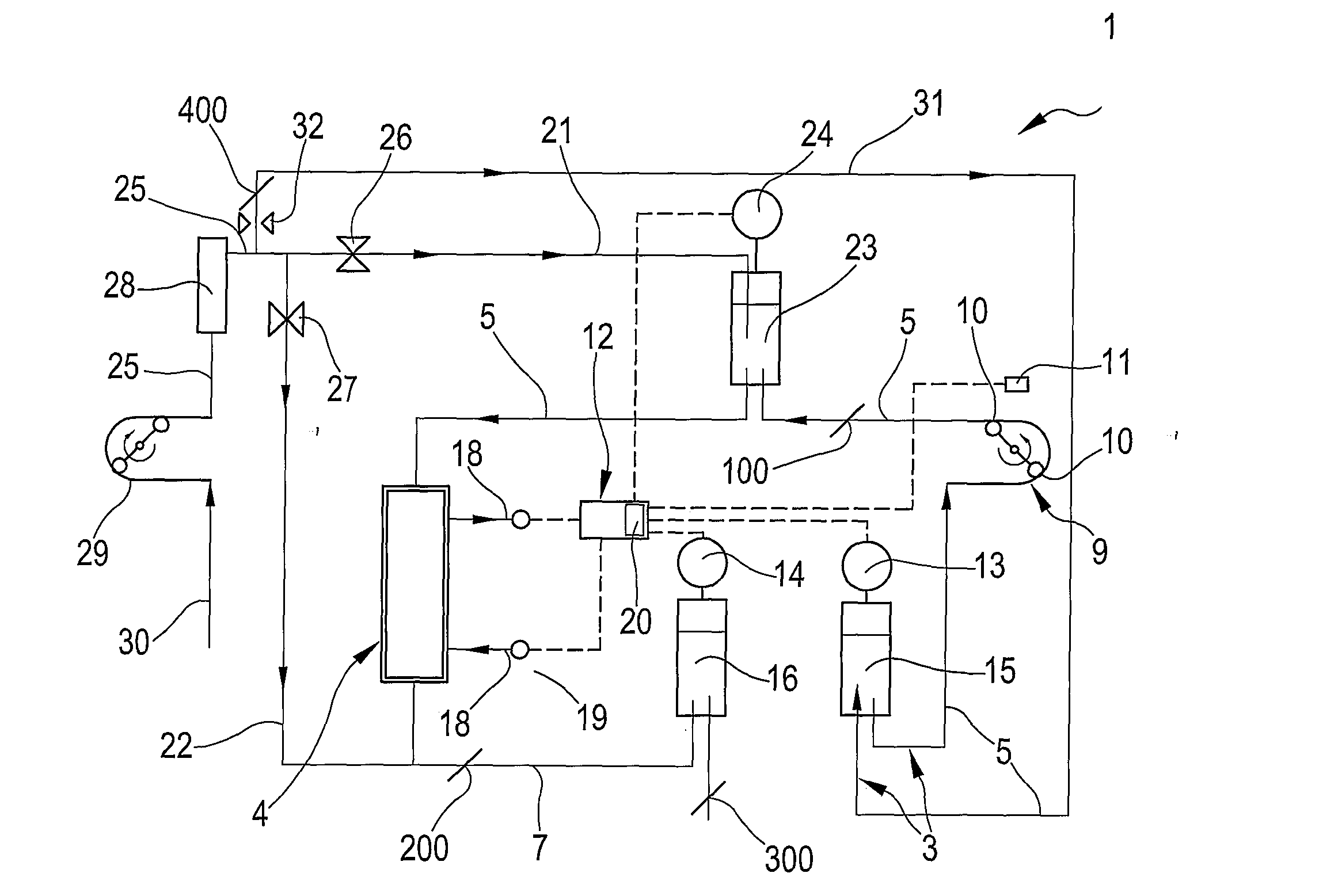
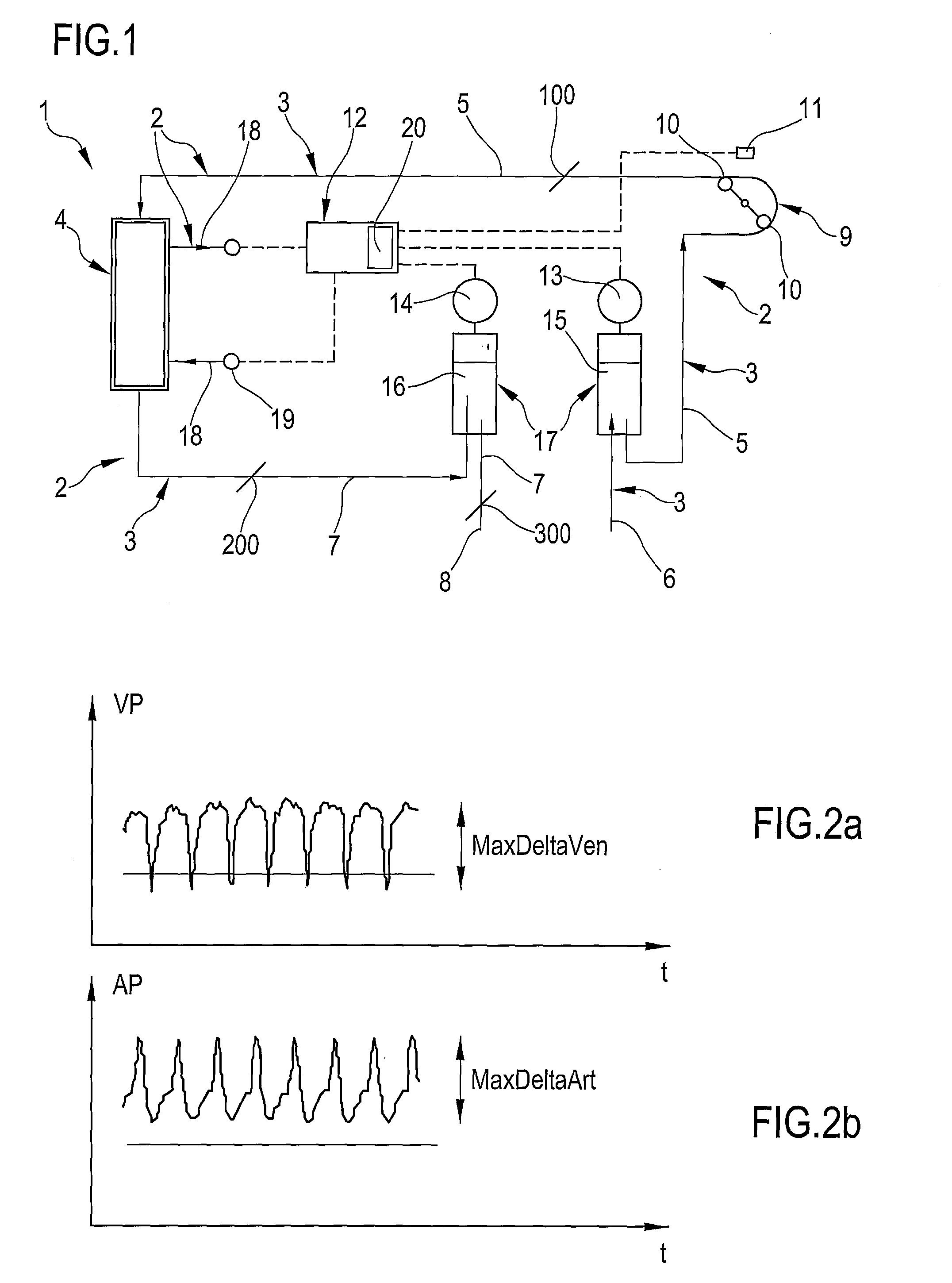
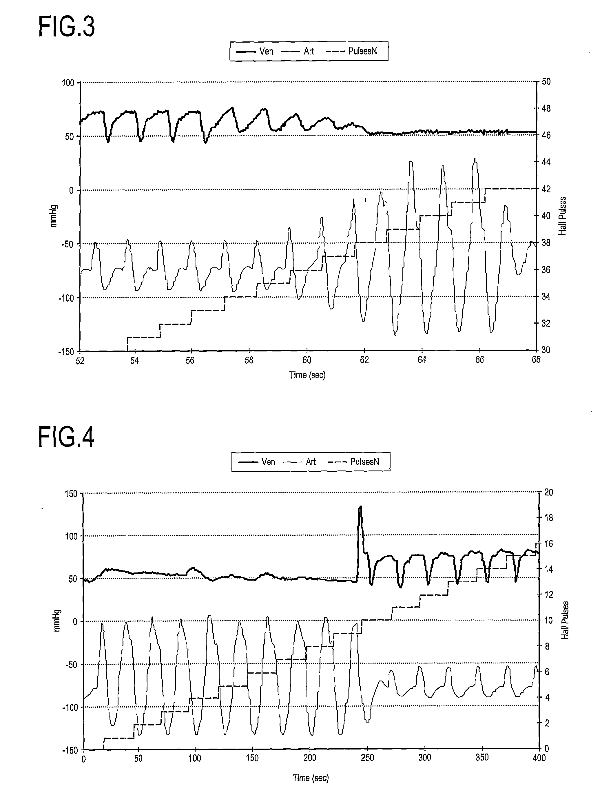
[0083]In a first embodiment, illustrated in figures from 1 to 7, the invention enables detection of a stenosis located at a first position of the blood line 3. A possible location of the first position is indicated in the figures with reference numeral 100, but the first position might be any position between the arterial expansion chamber and the treatment device 4 in the arterial line 5 or between the pump 9 and the treatment device 4.

[0084]In this first embodiment, the control device 12 receives from the pulse detection sensor 11 of the peristaltic pump 9 a signal corresponding to the passage of the rotor 10, and further receives, from the arterial blood pressure detection sensor 13, a pressure value measured in the arterial expansion chamber, and from the venous blood pressure detection sensor 14 a pressure value measured in the venous expansion chamber. A possible progression of venous and arterial pressure signals provided by the sensors, in normal operating conditions, is ill...

second embodiment

[0095]In the invention, illustrated in figures from 1 to 2 and from 8 to 10, the invention enables detection of a stenosis at a second position in the blood line 3. A possible location of the second position is denoted in the figures by reference numeral 200, but the second position could be anywhere along the venous line 7 between the treatment device 4 and the venous expansion chamber.

[0096]It is worthy of note that the second embodiment is actuated, as an example, with the machine in by-pass condition, i.e. with the treatment device 4 hydraulically disconnected from the hydraulic circuit. Generally the by-pass condition is not essential but guarantees only a better reliability during detection.

[0097]Consequently, in a case of occlusion in the venous line 7 between the treatment device (dialyser) and the venous expansion chamber, the increase in pressure in the side of the dialyser containing the treatment fluid is greater than the pressure increase in the venous expansion chamber...

third embodiment

[0103]In the invention, illustrated in FIGS. 1, 2, 8 and 11, the invention enables detection of a stenosis at a third position in the blood line 3.

[0104]A possible location of the third position is denoted in the figures with reference numeral 300, but the first position could be any position along the venous line 7 between the venous expansion chamber and the venous access 8 to the patient, i.e. along the venous line downstream of the venous expansion chamber. This third embodiment too is actuated with the machine in by-pass condition, i.e. with the treatment device 4 hydraulically disconnected from the hydraulic circuit. Also in this case, as in the previous one, the by-pass is not essential but makes the reading more reliable.

[0105]In this embodiment, the control device also receives, from the peristaltic pump 9 pulse detection sensor 11, a signal corresponding to the passage of the rotor 10. The control device 12 further receives, from the venous blood pressure detection sensor ...


PUM


Abstract

A method for monitoring a state of a blood line in a circuit for extracorporeal blood treatment, including the steps of: acquiring at least a first pressure value from a first sensor mounted at a first point of a circuit for extracorporeal blood treatment, comprising a blood line in which the blood is subjected to a pulsating thrust; acquiring at least a second pressure value from a second sensor mounted at a second point, distinct from the first point of the blood line of the circuit for extracorporeal blood treatment, and correlating at least a first value, correlated to the first pressure value, and at least a second value, correlated to the second pressure value, with at least a threshold value, in order to obtain a datum representing a state of the blood line.

Description

TECHNICAL FIELD[0001]The invention relates to a method and a corresponding device for monitoring a state of a blood line in a machine for extracorporeal blood treatment. Specifically, though not exclusively, the invention is applied in the medical field for monitoring the state of extracorporeal medical liquid and / or biological fluid flows. For example the invention can be applied in a hemodialysis or hemo(dia)filtration apparatus for detecting presence of any partial or total stenosis and occlusions in the blood removal line and / or return to or from a patient. A method and a device of the invention can also be applied in further applicational fields not described in detail in the present description.BACKGROUND OF THE INVENTION[0002]It is known that many fluid systems require precise measurement of the state of the system, and in particular various properties and / or parameters of the fluids flowing through them. In some of these systems measurements of single parameters are importan...

Claims


Application Information

Patent Timeline
IPC IPC(8): G01N33/49A61M1/14
CPCA61M1/3639A61M1/16A61M1/3622
Inventor SUFFRITTI, MAUROLIZZI, MARCO
Owner GAMBRO LUNDIA AB
Why Eureka
Eureka Blog
Learn More