
Sequential gear shifter

a gear shifter and gear shifter technology, applied in the direction of cycle actuators, vehicle transmissions, cycle equipment, etc., can solve the problems of high maintenance, large bodied, easy to damage, etc., and achieve the effects of easy manufacture, reliable, precise, and easy setting up and adjustmen

Pending Publication Date: 2019-09-19
CA TECH SYST
View PDF1 Cites 0 Cited by
  • Summary
  • Abstract
  • Description
  • Claims
  • Application Information

AI Technical Summary

Benefits of technology

The present invention is a new and improved gear shift system for speed change gear systems. It is reliable, precise, light-weight, robust, versatile, low-maintenance, easily set up and adjusted, easily manufactured, intuitively used, and lightly operated. The system allows independent and separate shifting towards a higher and a lower gear ratio, perpetual shifting in either direction, the possibility to switch shift directions with ease, and lever initiation from the same normal position every time. It also has instant shift engagement, a slim actuator well-protected from external impacts, a rigid and versatile interface with a wheel, and shifts many gear ratios in a single lever throw.

Problems solved by technology

However, twin wire systems are weighty, hard to adjust and to operate, high maintenance, and wide bodied.
Wide actuator bodies are placed outside the frame axle mounts, and are there vulnerable to impact damage.
While slim in design, continuous meshing limits the number of ratios that can be shifted per stroke, and requires adjustable ratcheting levers.
With binary shift torque, the number of gear ratio changes per air pressure release is limiting, and modulating the shift torque is impossible.
It also requires frequent re-pressurization.
From this discussion should be apparent a need for better gear shift systems for and that providing an attractive such mechanism represents a considerable technical challenge.

Method used


Image

  • Sequential gear shifter
  • Sequential gear shifter
  • Sequential gear shifter

Examples


Embodiment Construction

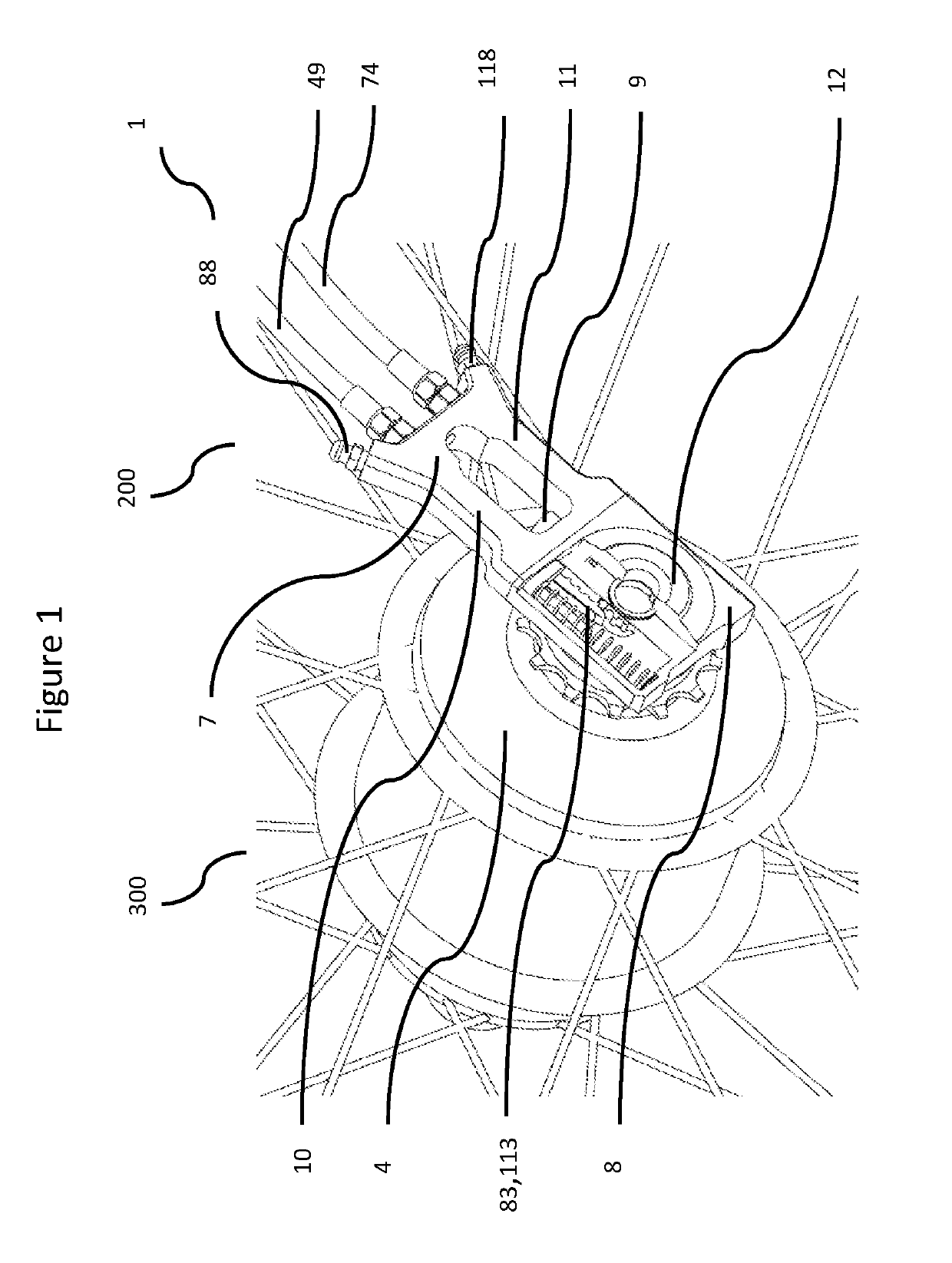
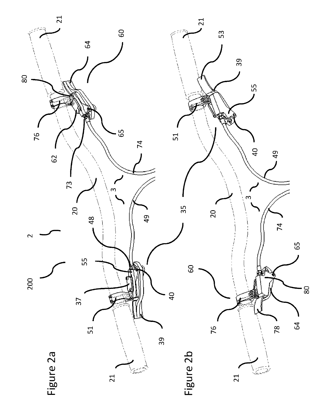
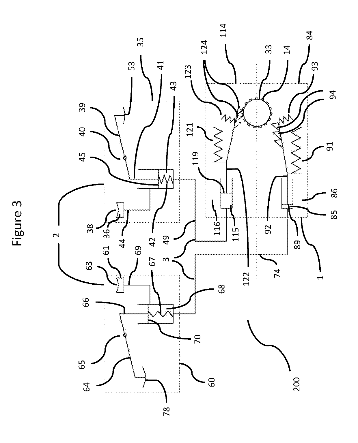
[0028]Referring initially to FIG. 1-3, a sequential gear shift system (200) for pedal driven vehicles comprises a single actuator device (1), an operator device (2) with two separate operator units (35, 60), and a transfer device (3) with two transfer units (49, 74), wherein the actuator (1) is connected with the operator units (35, 60) by means of the transfer units (49, 74). The gear shift system (200) allows the user to selectively shift the gear ratios of an internal speed change gear unit (4) (e.g. WO2012128639), and together these two (200, 4) comprise a gear system (300). The actuator (1) has an upper actuator housing (7) and a lower actuator housing (8), bolted together by means of a connection bolt (9), the upper housing (7) having a first and a second actuator pillar (10, 11), each in turn receiving a first and a second hydraulic cable (49, 74) which connect the actuator (1) to the operators (35, 60), and a first and second actuator bleed nipple (88, 118), and said lower h...


PUM


Abstract

A sequential gear shift system for two-way operated speed change gear units of manually propelled vehicles. Mirrored, spaced-apart lever operators, are provided with increasing lever stroke ratio, and actuate sequentially with twin mirrored one-way multi-tooth rack-clutch mechanisms, that rapidly engage with a shift element and convert linear torque to rotate the shift element in diametrically opposite directions. The rack-clutch mechanisms may be disengaged from the shift element when returning to normal. The actuating may occur via independent hydraulic operation of an actuator. The actuator housing and load bearing axle of the speed change gear hub are selectively, releasably, and coaxially interconnected into a rigid gear system load bearing axle, and may be combined at any angle, and a shift direction is selectively reversible.

Description

FIELD OF INVENTION[0001]The present invention relates to sequential gear shifters for pedally propelled vehicles, and means for shifting gear ratios and structurally supporting internal gear systems.BACKGROUND INFORMATION[0002]Gear shift systems for internal speed change gear units comprise in essence three parts or functions; an operator, transfer means, and an actuator. Operators with twist grips or levers send signals by means of cables, rods, gases, fluids, or electrical impulses to the actuator, that interprets and converts shift signals by means of e.g. racks and gears, rods, pivoting quadrangular rhomboids, rotatable shift sleeves, and piggyback converter units, into a motion desired, e.g. sliding of rods or circumferential rotation of sleeves.[0003]Advanced two-way gear units are shifted by reciprocating twist-operators, with an incoming spool for collecting wire, an actuator with a corresponding spool, and twin cable transfer devices with an inner wire stretching from the o...

Claims


Application Information

Patent Timeline
IPC IPC(8): B62M11/06
CPCB62M25/08B62M25/04B62M9/06B62M11/08B62M9/04B62M11/04B62M11/16
Inventor LJØSNE, KNUT TOREANTAL, CHRISTIAN
Owner CA TECH SYST
Learn More