Optical Receiver

a receiver and optical technology, applied in the field of optical receivers, can solve the problems of difficult to carry out precise demodulation, high complexity of the control system of the respective interferometer, and the difference in optical path length in the respective interferometer, so as to simplify the control system, suppress the adverse effect, and easily demodulate the i-component signal

Inactive Publication Date: 2012-11-29
SUMITOMO OSAKA CEMENT CO LTD
View PDF3 Cites 4 Cited by
  • Summary
  • Abstract
  • Description
  • Claims
  • Application Information

AI Technical Summary

Benefits of technology

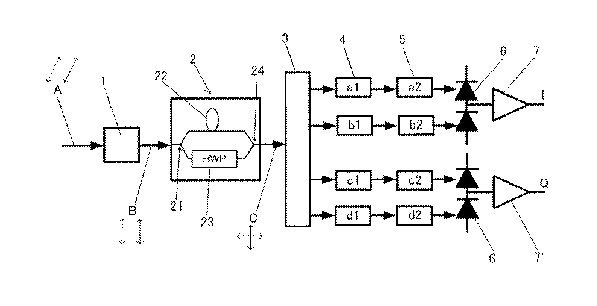
[0017]According to the first aspect of the invention, an optical receiver that demodulates an optical signal modulated in a DQPSK manner to a multi-level phase-modulated signal includes interference means for branching the optical signal modulated in a DQPSK manner into two light beams, delaying at least one branched light beam so that two branched light beams have a predetermined phase difference, rotating the polarization plane of at least one branched light beam so that the polarization planes of the two branched light beams are orthogonal to each other, and coupling the two branched light beams, light separation adjusting means for separating the output light beam from the interference means and adjusting the polarization planes of the separated light beams, and detection means for detecting light intensities of the separated light beams output from the light separation adjusting means, and generates an I-component signal and a Q-component signal on the basis of detection signals from the detection means. Accordingly, it is possible to demodulate an I-component signal and a Q-component signal using only one interference means. Since only one interference means is used, it is necessary to adjust only one optical path length in the interference means so as to achieve high-precision demodulation and it is possible to greatly simplify a control system.
[0018]According to the second aspect of the invention, the light separation adjusting means includes light separation means for separating the output light beam from the interference means into four light beams, 
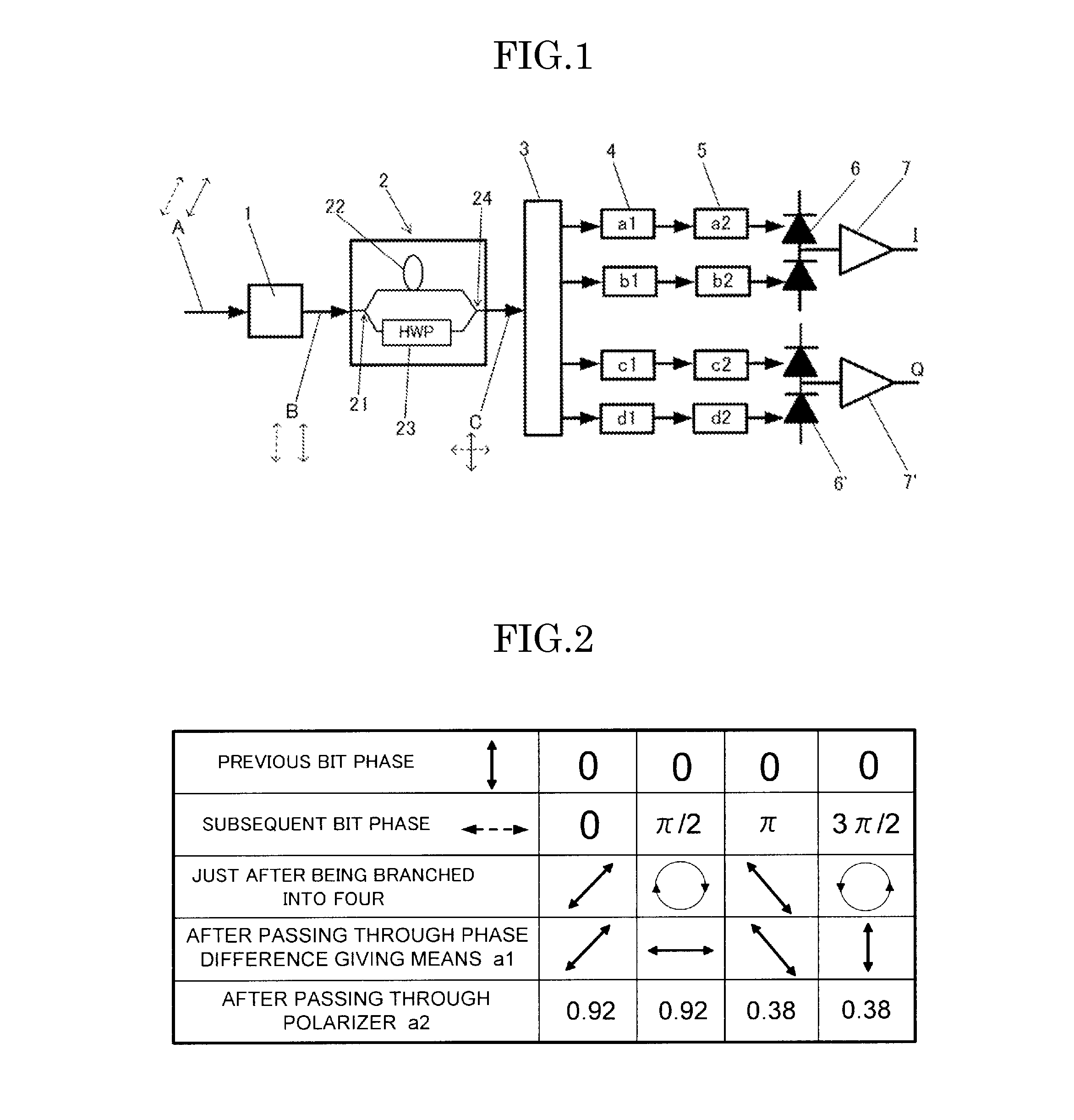
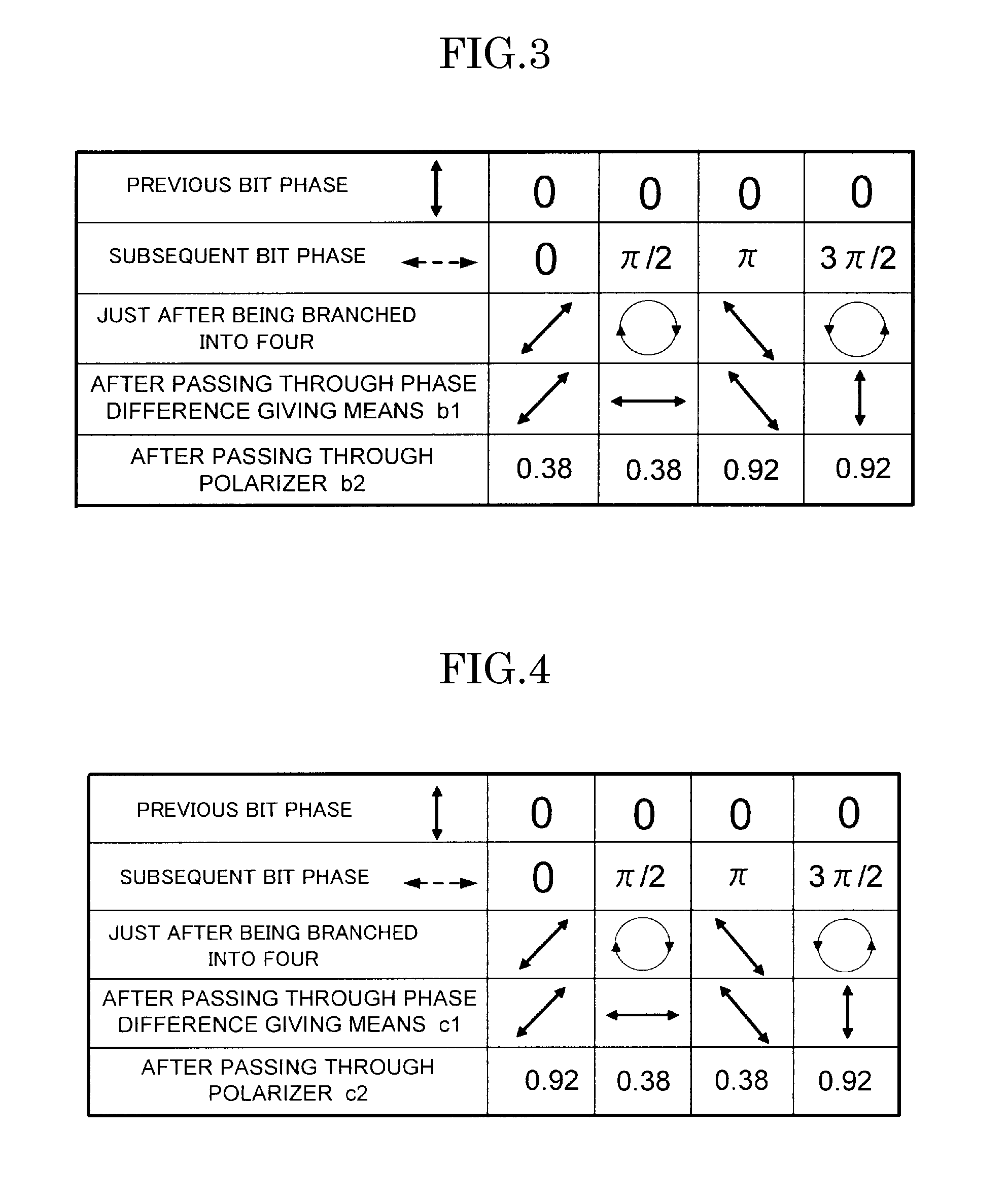
phase difference giving means for giving a phase difference at 45 degrees or 225 degrees to the polarization planes of two separated light beams among four separated light beams from the separation means and giving a phase difference at 135 degrees or 315 degrees to the polarization planes of the other two separated light beams, a polarizer that has a transmissive polarization plane of 22.5 degrees or 202.5 degrees for one of the two separated light beams to which the phase difference at 45 degrees or 225 degrees has been given and a transmissive polarization plane of 112.5 degrees or 292.5 degrees for the other thereof, and a polarizer that has a transmissive polarization plane of 22.5 degrees or 202.5 degrees for one of the two separated light beams to which the phase difference at 135 degrees or 315 degrees has been given and a transmissive polarization plane of 112.5 degrees or 292.5 degrees for the other thereof. Accordingly, it is possible to easily demodulate an I-component signal and a Q-component signal from the output light beam from the single interference means. Since there can be optimal setting such that plural optical waves in each stage have different polarization planes, it is possible to suppress an adverse effect that neighboring polarization planes interfere to degrade signals, and the like.
[0019]According to the third aspect of the invention, the light separation adjusting means includes light separation means for separating the output light beam from the interference means into two light beams, phase difference giving means for giving phase differences of different angles to the polarization planes of the separated light beams from the light separation means, and splitting means for splitting the respective separated light beams having different polarization planes into two separated light beams having different components of the polarization plane. Accordingly, it is possible to easily demodulate an I-component signal and a Q-component signal from the output light beam from only one interference means.
[0020]According to the fourth aspect of the invention, the light separation adjusting means includes light separation means for separating the output light beam from the interference means into two light beams, phase difference giving means for giving a phase difference at a same angle to the polarization planes of the separated light beams from the separation means, and splitting means for splitting the respective separated light beams having the same polarization plane into two separated light beams having different components of the polarization plane. Accordingly, it is possible to easily demodulate an I-component signal and a Q-component signal from the output light beam from only one interference means.
[0021]According to the fifth aspect of the invention, the light separation adjusting means includes phase difference giving means for giving a phase difference at a predetermined angle to the polarization plane of the output light beam from the interference means, light separation means for separating the output light beam from the phase difference giving means into two light beams, and splitting means for splitting the respective separated light beams into two separated light beams having different components of the polarization plane. Accordingly, it is possible to easily demodulate an I-component signal and a Q-component signal from the output light beam from only one interference means.
[0022]According to the sixth aspect of the invention, since polarization adjusting means for adjusting an angle of the polarization plane of the optical wave input to the interference means is disposed on an optical path in front of the interference means, it is possible to further accurately adjust the rotation of the polarization planes in the interference means and to further accurately realize the orthogonal relationship between the polarization planes of two branched light beams.

Problems solved by technology

However, since the optical path lengths in the delay interferometers vary and the phase is not stable due to the influence of the ambient temperature or the like of the optical receiver, it is difficult to carry out precise demodulation.
There is also a problem in that through which interferometer to demodulate which signal component is not known.
There is also a problem in that it is necessary to optimally adjust the difference in optical path length until an optical signal is separated and is input to two interferometers or the difference in optical path length in the respective interferometers and the control system thereof is highly complicated.

Method used


Image

  • Optical Receiver
  • Optical Receiver
  • Optical Receiver

Examples


Embodiment Construction

[0036]Hereinafter, the invention will be described in detail with reference to exemplary embodiments.

[0037]As shown in FIG. 1, the invention provides an optical receiver that demodulates an optical signal A modulated in a DQPSK manner to a multi-level phase-modulated signal, including interference means 2 for branching the optical signal modulated in a DQPSK manner into two light beams, delaying at least one branched light beam so that two branched light beams have a predetermined phase difference, rotating the polarization plane of at least one branched light beam so that the polarization planes of the two branched light beams are orthogonal to each other, and coupling the two branched light beams, light separation adjusting means 3 to 5 for separating the output light beam from the interference means and adjusting the polarization planes of the separated light beams, and detection means 6 and 6′ for detecting light intensities of the separated light beams output from the light sep...


PUM


Abstract

An optical receiver includes interference means 2 for branching the optical signal modulated in a DQPSK manner into two light beams, delaying at least one branched light beam so that two branched light beams have a predetermined phase difference, rotating the polarization plane of at least one branched light beam so that the polarization planes of the two branched light beams are orthogonal to each other, and coupling the two branched light beams, light separation adjusting means 3 to 5 for separating the output light beam from the interference means and adjusting the polarization planes of the separated light beams, and detection means 6 and 6′ for detecting light intensities of the separated light beams output from the light separation adjusting means, wherein an I-component signal and a Q-component signal are generated on the basis of detection signals from the detection means.

Description

TECHNICAL FIELD [0001]The present invention relates to an optical receiver, and more particularly, to an optical receiver that demodulates an optical signal modulated in a DQPSK manner to a multi-level phase-modulated signal.BACKGROUND ART [0002]In next-generation long-distance large-capacity optical communication systems requiring an increase in speed and an increase in capacity with an increase in communication traffic, the introduction of multi-level modulation-demodulation encoding techniques has been studied. A representative example thereof is a differential quadrature phase shift keying (DQPSK) modulation method. In this method, the signal band is narrower than that in a binary intensity modulation (OOK) method, thus it is possible to improve frequency utilization efficiency or to extend a transmission distance, and an increase in sensitivity can be also expected.[0003]In a quadrature phase shift keying (QPSK) modulation method, “θ”, “θ+π / 2”, “θ+π”, and “θ+3π / 2” are allocated...

Claims


Application Information

Patent Timeline
Patent Type & Authority Applications(United States)
IPC IPC(8): H04B10/06H04B10/67
CPCH04B10/677
Inventor MURE, MASAHITOHIGUMA, KAORUKATAOKA, TOSHIOMIYAZAKI, NORIKAZUMIYACHI, MASAHIDEOIKAWA, YOUICHISHIGA, NORIYASUNAGAEDA, HIROSHI
Owner SUMITOMO OSAKA CEMENT CO LTD
Why Eureka
Try Eureka