Transceiver with sub - sampling based frequency synthesizer

a frequency synthesizer and sub-sampling technology, applied in the field of transceivers, can solve the problems of noise deteriorating the spectral purity of the lo signal, phase error signal on the output of the phase detector, and generating some output frequencies, so as to improve the spectral purity of the synthesizer output signal

Active Publication Date: 2014-02-06
QORVO INT PTE LTD
View PDF8 Cites 4 Cited by
  • Summary
  • Abstract
  • Description
  • Claims
  • Application Information

AI Technical Summary

Benefits of technology

[0016]The object of the invention is to provide an improved transceiver, with respect to at least one of the problems described above. The object of the invention is further to

Problems solved by technology

A phase difference will result in a phase error signal on the output of the phase detector.
Especially for high-frequency synthesizers this noise deteriorates the spectral purity of the LO signal.
However a disadvantage to this sub-sampling based architecture is that for generating some output frequencies sub-sampling does not work.
However, normally a transceiver has to operate at a multitude of channels and thus has to be able to generate a multitude of RF output signals.
Using different sampling frequencies for generat

Method used


Image

  • Transceiver with sub - sampling based frequency synthesizer
  • Transceiver with sub - sampling based frequency synthesizer
  • Transceiver with sub - sampling based frequency synthesizer

Examples


Embodiment Construction

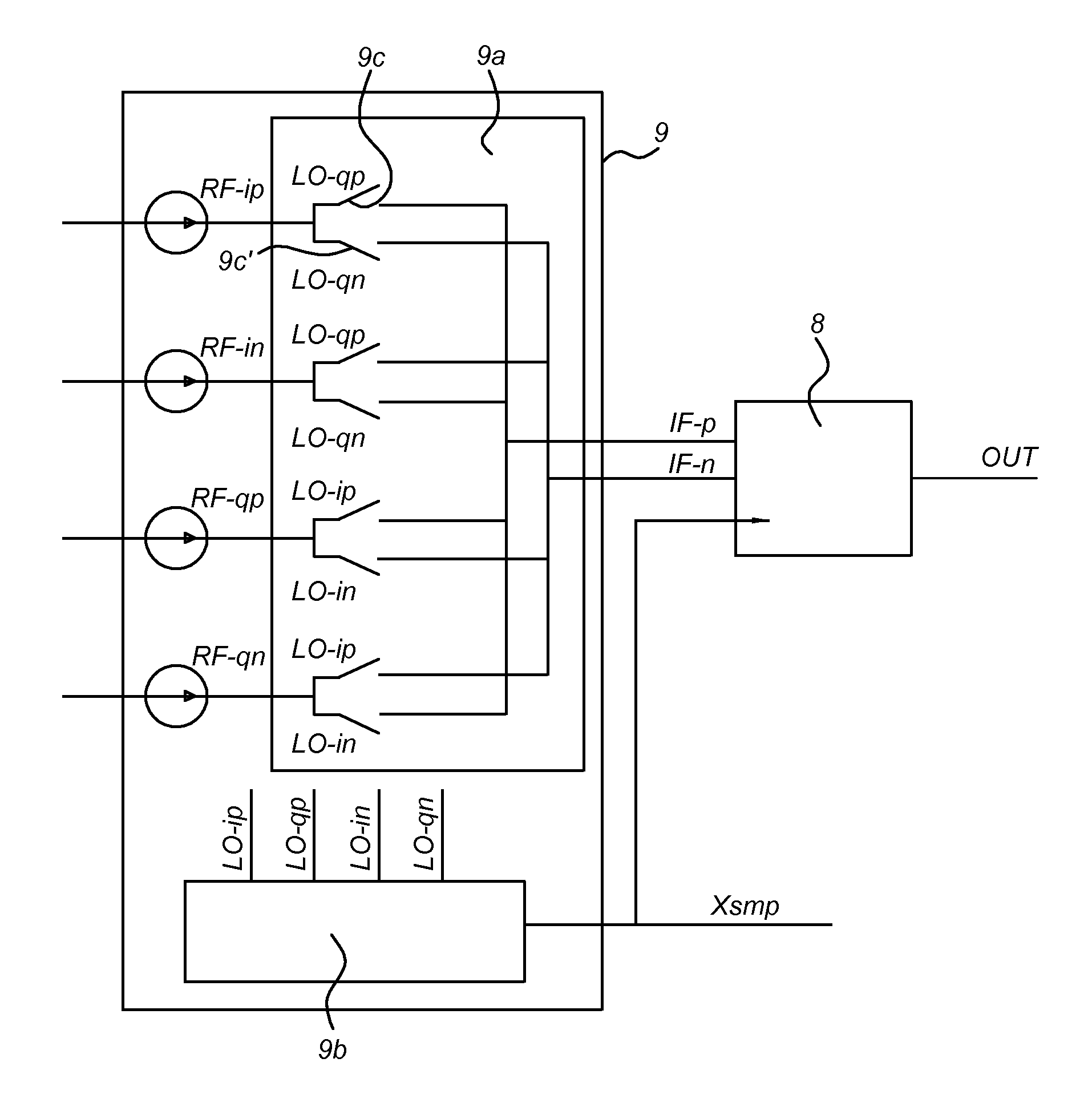
[0039]According to the invention and the following description the term “sub-sampling based” means that the output signal 3 of the frequency synthesizer having a frequency fout is sampled with a sampling unit with a sampling frequency fsmp to obtain a time discrete signal, wherein fsmpout. By sub-sampling or under-sampling the frequency fout is mapped to a frequency fbs in the range from −fsmp / 2 to +fsmp / 2. By sub-sampling, the power consuming frequency division unit or counters counting the zero crossings or cycles in the output signal of the frequency synthesizer are replaced by a sampler which consumes considerably less energy. For an IEEE 802.15.4 transceiver fout has a frequency in the range of the 2.4 GHz band. In the embodiment described below a sampling frequency of 16 MHz is used.

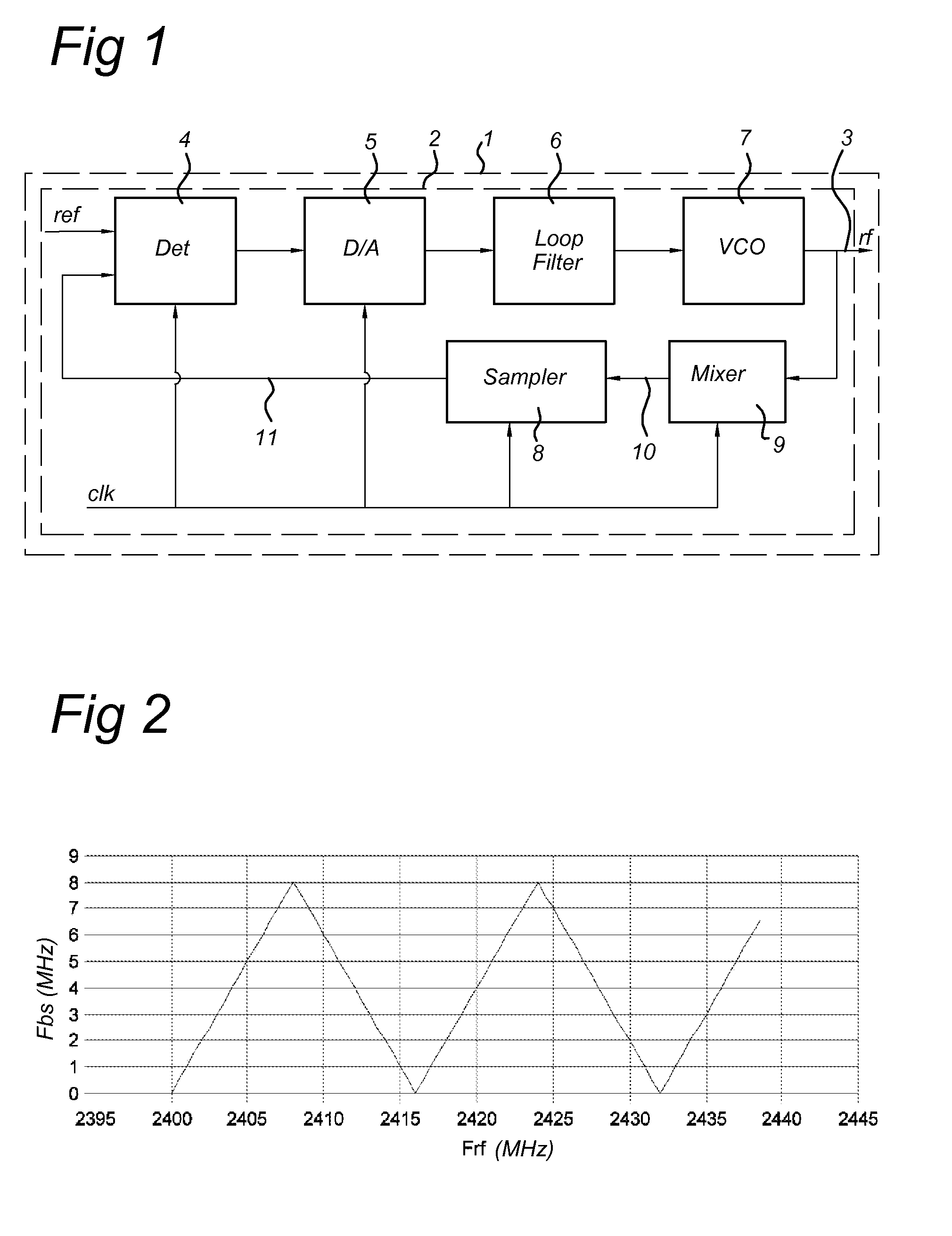
[0040]FIG. 1 shows a block diagram of a frequency synthesizer 2 according to the invention. The frequency synthesizer comprises a feedback loop with the following components: a frequency or phase d...


PUM


Abstract

Disclosed is a transceiver including a sub-sampling based frequency synthesizer with a sampling frequency fsmp, configured to generate M different output signals 3 for use as a carrier signal for transmission and/or a signal with a channel frequency for reception. M is an integer greater than 4, each output signal has a corresponding predefined frequency. The predefined frequencies are within a frequency band with a predefined bandwidth CFR. CFR is greater than fsmp. The frequency synthesizer includes a frequency shift unit configured for shifting a version of the output signal over a predefined frequency shift fshift to obtain a frequency shifted signal which is supplied to a sampling unit of the sub-sampling based frequency synthesizer, wherein −fsmp/2≦fshift≦+fsmp/2. The frequency shift unit is configured to use for the generation of each of the N different output signals a corresponding predefined frequency shift fshift.

Description

TECHNICAL FIELD OF THE INVENTION[0001]The invention relates to a transceiver, more particular to a transceiver with low power consumption, more particular to an IEEE 802.15.4 transceiver. The invention further relates to frequency synthesizer for use in a transceiver, more particular a frequency synthesizer with low power consumption, more particular to a frequency synthesizer for use in an IEEE 802.15.4 transceiver.BACKGROUND OF THE INVENTION[0002]Frequency synthesizers utilized in known radio frequency (RF) communication devices, such as a RF transmitter, have included a voltage controlled oscillator and a reference oscillator coupled together in a phase locked loop. A voltage-controlled oscillator or VCO is an electronic oscillator designed to be controlled in oscillation frequency by a voltage supplied to a control input. The frequency of oscillation fvco depends on the applied DC voltage. The VCO frequency is divided by a 1 / N divider to a frequency comparable to a reference fre...

Claims


Application Information

Patent Timeline
IPC IPC(8): H03B21/00
CPCH03B21/00H03L7/16H03L2207/12H04B1/408H04B1/40
Inventor ROODNAT, ANTON WILLEMVAN DRIEST, HANSHAANSTRA, JAN HENDRIK
Owner QORVO INT PTE LTD
Why Eureka
Try Eureka