System and method for managing utility consumption
a utility consumption and system technology, applied in adaptive control, process and machine control, instruments, etc., can solve the problems of high utility consumption costs, damage to electric motors and other equipment, and overburden of electrical utility grids by heavy air conditioner usage, etc., to reduce peak demand
- Summary
- Abstract
- Description
- Claims
- Application Information
AI Technical Summary
Benefits of technology
Problems solved by technology
Method used
Image
Examples
embodiment 226
[0052]Referring now to FIG. 6, an embodiment 226 of a packaged switch 218 and sensor 220 is shown. Switch 218 is operable by a signal 606 from a computing device. In another embodiment, as discussed above, manual input may be provided for as well. Sensor 220 measures utility consumption 602, and is further encoded with an identification code 604 for its associated load. Output 608 of measured consumption 602 and ID 604 are provided to the computing device. Such provision may occur at scheduled intervals, upon request by the computing device, or upon initiation by the switch / sensor unit.
[0053]FIG. 7 shows another embodiment 226′ of a packaged switch 218′ and sensor 220′. Sensor 220′ measures utility consumption 702 and is further encoded with ID 704 for its associated load. Computing device 706, in combination with sensor 220′, provides for tracking the time 708 and duration 710 of utility consumption. The computing device also provides, with switch 218′, provision for override 711 o...
embodiment 800
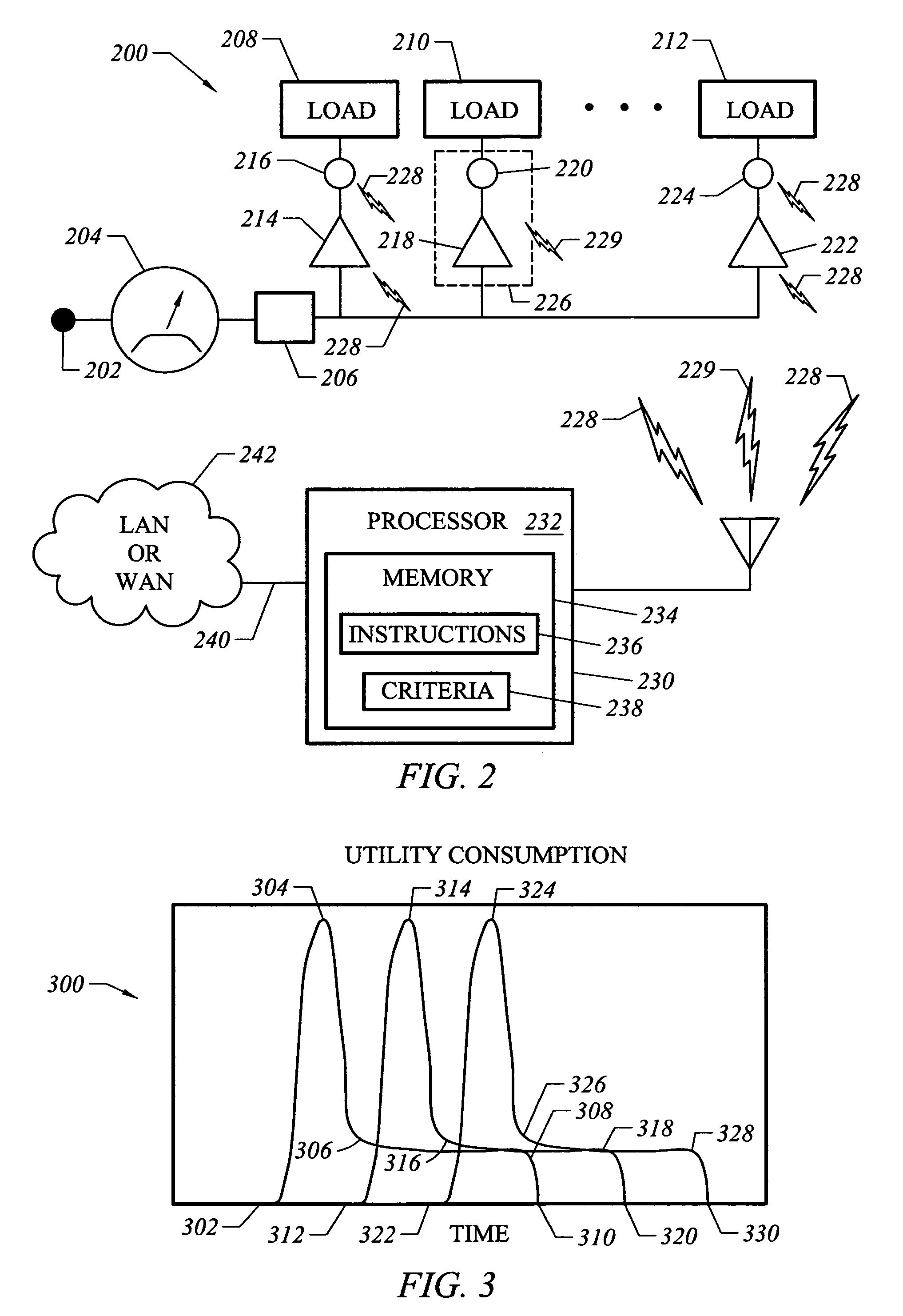
[0056]In the embodiment 800 shown in FIG. 8, for clarity, some elements shown in FIG. 2 have been omitted. Units of utility consumption provided by a supply 202 pass through a utility meter 204. In the case of electric power, a breaker box or other safety device for preventing overconsumption is provided at 206.
[0057]A storage / conversion unit at 802 appears as a load to supply 202. A utility intertie or utility interface 804 ensures against backfeeding, in embodiments in which supply 202 is electrical. In FIG. 8, interface 804 appears in combination with the breaker box / safety device labeled 206 in FIG. 2.
[0058]A monitor unit 806 tracks consumption at the utility meter. Data from module 806 is provided to a control unit 808. Control unit 808 provides commands to storage / conversion unit 802 on whether to draw utility consumption units, and thus act as a load on supply 202.
[0059]Alternatively, control unit 808 provides commands to storage / conversion unit 802 to convert from stored for...
embodiment 1000
[0063]FIG. 10 shows a flowchart of a method for monitoring and turning off idle devices in accordance with an embodiment 1000. In a step 1010, utility consumption at a current time is monitored for each load having a standby mode. At 1020, historical data from a database is used to derive a shutdown criterion for each load at the current time. For example, the mean time between user requests to activate a particular device may be derived from data retrieved from the database. Other statistical measures may be used to provide a criterion for load shutdown. In a step 1030, if a load is currently in standby mode, and the current duration of standby mode for that load exceeds the shutdown criterion for that load, the load is shut down. Continual monitoring 1040 of devices having standby mode may take place in this embodiment.
[0064]FIG. 11 shows a flowchart for a method for managing storage and conversion of one utility into another and back again, at 1100, in accordance with an embodime...
PUM
 Abstract
Description
Claims
Application Information
 - R&D
- Intellectual Property
- Life Sciences
- Materials
- Tech Scout
- Unparalleled Data Quality
- Higher Quality Content
- 60% Fewer Hallucinations
Browse by: Latest US Patents, China's latest patents, Technical Efficacy Thesaurus, Application Domain, Technology Topic, Popular Technical Reports.
© 2025 PatSnap. All rights reserved.Legal|Privacy policy|Modern Slavery Act Transparency Statement|Sitemap|About US| Contact US: help@patsnap.com


