Method to detect utility disturbance and fault direction

a utility and fault direction technology, applied in the direction of computer control, ac network load balancing, instruments, etc., can solve the problems of inability to meet other important capacity constraints in the distribution grid, inability to leverage des to meet other important capacity constraints, and high cost of transformers in these substations. to achieve the effect of facilitating the connection of various renewable energy sources

Active Publication Date: 2020-12-15
S&C ELECTRIC
View PDF3 Cites 5 Cited by
  • Summary
  • Abstract
  • Description
  • Claims
  • Application Information

AI Technical Summary

Benefits of technology

[0004]The primary function of the DES unit is to assist the utility in reducing peak demand (referred to commonly as “peak shaving” or “load following”) to defer or eliminate a regional need for additional generating capacity, although the DES unit has many other valuable features. These include the ability to provide reactive power compensation, to provide backup power for stranded customers when the main source of supply is temporarily unavailable, and to provide frequency support (ancillary services). An extensive description of the requirements of the basic DES unit, from the customer (electric distribution utility) point of view is contained in the EPRI DES Hub and Unit Functional Requirements Specifications. Other functions allow the DES unit to facilitate the connection of various renewable energy sources into the grid. This includes providing energy storage or buffering during periods of weak demand, and conversion from DC to AC and AC to DC.
[0010]The deployment of new energy sources near the energy consumer, under direct control of the utility, presents other opportunities for improvement in power distribution capacity management as well. Historically, capacity management has been primarily based upon static, worst-case estimates of circuit loading applied to models of electrical characteristics of the distribution system. The fundamental goal of this analysis is to protect the electrical components from damage due to overheating. However, once the capacity, measured in amperes or watts, has been established, the primary monitoring, if any, is based on real-time measurements of current or power rather than on heat. In overhead distribution, where the load is carried on individual conductors consisting of bare wire, the analysis is relatively accurate and foolproof.
[0014]The combination of a new means to selectively reduce distribution system loading, combined with the technologies of thermal sensing systems could allow for new, “semi-closed loop” control of the electrical distribution supply system based upon control of energy to meet thermal loading requirements. Such a control system should respond to capacity constraints at all three levels (regional, substation transformer and feeder capacity), even if present simultaneously, should be capable of optionally using the new temperature sensing technologies, and should attempt to even the wear due to repeated discharge / charge cycles over all storage units in the system.

Problems solved by technology

As a result of the rapid emergence and convergence of these new technologies and others, little attention has been placed on how DES could be leveraged to meet other important capacity constraints in the distribution grid.
That is, not all capacity constraints are related to peak demand for generation capacity.
For example, the 
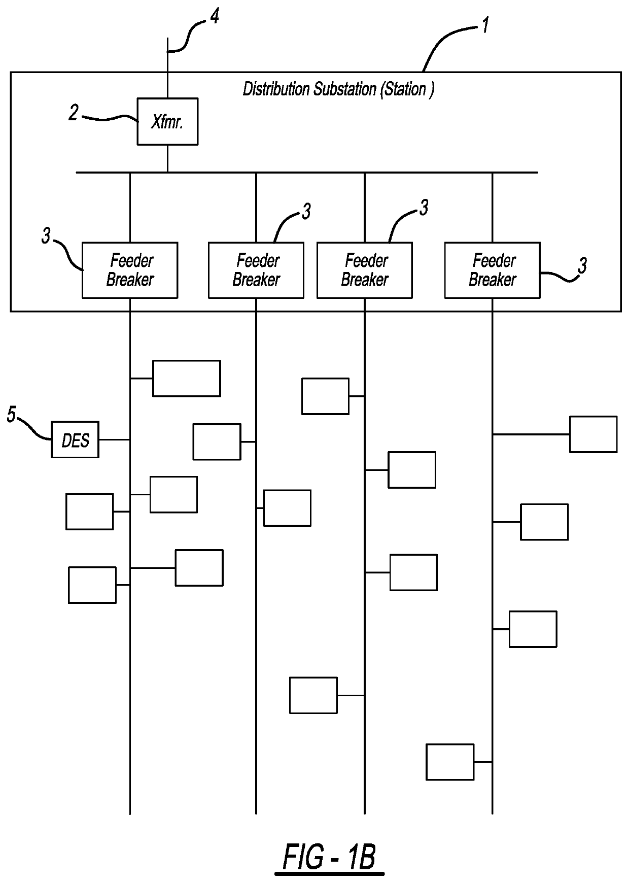
distribution system is fed from distribution substations, and the transformers in these substations are extremely costly and difficult to replace.
Capacity constraints in these transformers, or loss of capacity due to end of life or other operational issues, can create overheating (hot spots), leading to unexpected failure and concomitant risk of service interruption.
Another capacity constraint is the distribution feeder itself, particularly in the most-heavily utilized sections near the substation.
Underground, high-voltage cable is very expensive, heat sensitive and replacement is even more problematic than substation transformers.
On the other hand, a substation transformer capacity limitation is inherently phase-specific.
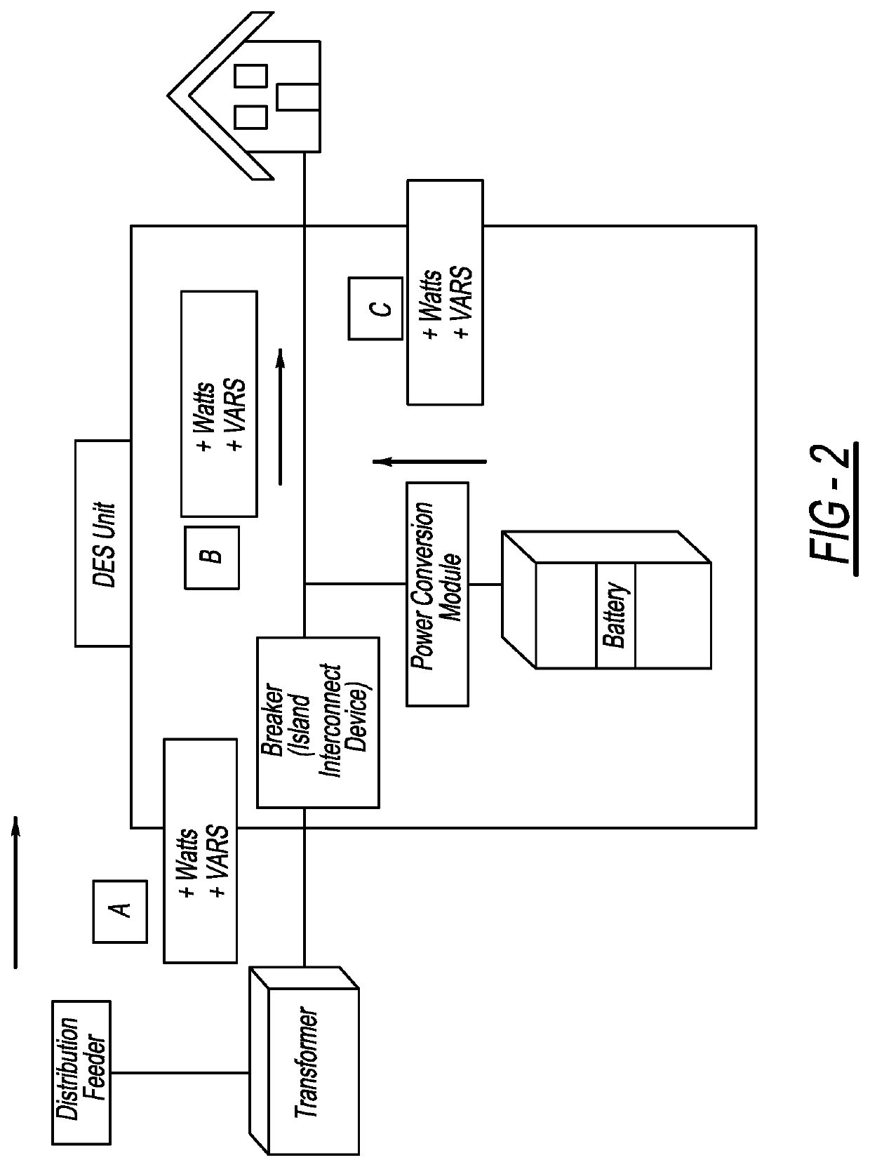
For example, using DES units, a capacity limitation on Phase A, being specific to Phase A, can only be addressed by reducing loading on Phase A. However, a DES unit downstream from the transformer on any feeder could discharge energy to reduce load as long as it was on Phase A. In contrast, a capacity limitation sensed at the head of a single phase of a feeder can only be addressed by shifting load to DES units on that phase and on that feeder.
There are several other complications to DES energy dispatch.
It's possible that multiple capacity constraints, particularly at times of near brownout or blackout conditions, may exist simultaneously.
Under this scenario, complex decision-making may be necessary to prioritize and mediate the various constraints.
Since these units are geographically dispersed there is a need to level out the usage of the units to prevent over-utilizing or exclusively-utilizing specific units, requiring premature battery replacement in those units, while failing to gain benefit from the investment in other units.
The analysis of capacity based on component overheating is much more complicated when the components are packaged or in some way thermally constrained.
For example, the thermal analysis of power flow and capacity of a substation transformer is extremely complex.
The individual windings of the transformer are typically immersed in oil, adjacent to, and influenced by the other windings, and affected by very complex electrical phenomenon such as the internal absorption of power flow harmonics, circuit imbalance, power factor and aging of components.
Because of the substantial expense and customer service impacts of a transformer failure, these derating factors tend to be very conservative.
Due to the inherent variability of the above factors, even with the best design tools, the true, real-time capacity of the distribution system can only be guessed.
However, without the ability to immediately reduce load when this point is reached, the distribution system operator must either allow the transformer to be damaged and risk catastrophic failure, or temporarily disconnect customers from service.
The challenge of estimating and monitoring the capacity of underground feeder is even more complex than of the substation transformer.
Dense runs of insulated conductor in conduit, in confined air spaces, adjacent to other potentially heat-generating cable, surrounded by thermally insulating earth, can create unpredictable and unexpectedly-high operating temperatures.
Even with sophisticated programs such as CYMCAP™, precise cable capacity estimation is difficult for a variety of reasons such as variations in the thermal insulating properties of the earth along the feeder.
As with the capabilities of transformer hot spot monitoring, lacking the ability to immediately reduce load when the real-time thermal capacity is reached, the distribution system operator must either allow the cable to be damaged and risk catastrophic failure, or temporarily disconnect customers from service.
However, unlike transformer overloading that could be mitigated with substation energy storage, feeder overloading can only be mitigated by reduction of load (such techniques are usually referred to as “demand reduction” or DR) or generation of energy on the feeder using a system such as distributed storage.
However, due to the small size of the DES units, even with only RPC active, the total compensation on a feeder is only slightly larger than a single 1,800 kVAR switched capacitor bank.
During peak loading, when DES is needed for real power peak shaving, very little residual RPC is available.

Method used


Image

  • Method to detect utility disturbance and fault direction
  • Method to detect utility disturbance and fault direction
  • Method to detect utility disturbance and fault direction

Examples


Embodiment Construction

[0034]An embodiment of a DES system is shown in FIG. 1a. Connectors depicted in the drawings indicate information exchange between components. The DES units (1) are assembled or prepackaged components or boxes including energy storage modules (batteries in the present system). The system could use virtually any form of energy storage, including kinetic, capacitive, chemical, etc., as long as it is locally-convertible by the unit to electrical energy on demand. The DES units also include a four-quadrant inverter and digital computer-based control with the ability to communicate to the outside world. The present units utilize the open standard DNP3 communication protocol to communicate to the Hub Controller (“Hub”) (2) although modern computer technology provides a wide variety of application protocols that could be used. Since the DES units are dispersed over a wide geographic area, a radio communication system (3) is preferentially utilized to facilitate the information exchange wit...


PUM


Abstract

A method for detecting a voltage disturbance in a utility having a micro-grid. The method transforms current and voltage measurements into first and second voltage values and first and second current values in a stationary reference frame, and transforms the first and second voltage values and the first and second current values to third and fourth voltage values and third and fourth current values in a rotating reference frame, where the third voltage value defines an average magnitude of the three-phase power signals. The method multiplies the third current value by the third voltage value to obtain an instantaneous power value and multiplies the fourth current value by the third voltage value to obtain an instantaneous volt-ampere reactive (VAR) value. The method opens the switch if the VAR value has a magnitude above a predetermined value and a direction indicating the fault is outside of the micro-grid in the network.

Description

CROSS-REFERENCE TO A RELATED APPLICATIONS[0001]This application is continuation of prior U.S. application Ser. No. 14 / 399,534, filed Jun. 29, 2015, which is a U.S. national stage entry of International Application Number PCT / US2012 / 023422, filed Feb. 1, 2012, which claims priority of U.S. Patent Application Nos. 61 / 438,507, 61 / 438,517, 61 / 438,525 and 61 / 438,534 filed Feb. 1, 2011, which are all hereby incorporated herein by reference in their entirety.TECHNICAL FIELD[0002]This patent provides apparatus and methods to control and coordinate a multiplicity of electric distribution grid-connected, energy storage units deployed over a geographically-dispersed area.INTRODUCTION[0003]This patent describes embodiments of systems, apparatus and methods to provide improved control and coordination of a multiplicity of electric distribution grid-connected, energy storage units deployed over a geographically-dispersed area. The units may be very similar to those described in U.S. Pat. No. 6,90...

Claims


Application Information

Patent Timeline
Patent Type & Authority Patents(United States)
IPC IPC(8): H02J3/32G05B15/02H02J3/18
CPCG05B15/02H02J3/1807H02J3/32Y02E40/30
Inventor PORTER, DAVID GLENNWILLIAMS, STEPHEN E.
Owner S&C ELECTRIC
Why Eureka
Try Eureka