Method and system for enhanced verification through structural target decomposition

a technology of structural target decomposition and verification method, applied in the field of verification designs, can solve the problems of hardware verification becoming one of the most important and time-consuming aspects of the design process, consumers of circuit products have lost tolerance for results polluted by design errors, and medical devices cannot tolera

Inactive Publication Date: 2008-03-25
GOOGLE LLC
View PDF1 Cites 9 Cited by
  • Summary
  • Abstract
  • Description
  • Claims
  • Application Information

AI Technical Summary

Problems solved by technology

Whether the impact of errors in design would be measured in human lives or in mere dollars and cents, consumers of circuit products have lost tolerance for results polluted by design errors.
Consumers will not tolerate, by way of example, miscalculations on the floor of the stock exchange, in the medical devices that support human life, or in the computers that control their automobiles.
The task of hardware verification has become one of the most important and time-consuming aspects of the design process.
Unfortunately, the resources needed for formal verification, or any verification, of designs are proportional to design size.
Semi-formal verification techniques leverage formal methods on larger designs by applying them only in a resource-bounded manner, though at the expense of incomplete verification coverage.
Such techniques tend to rely upon binary decision diagram-based or Boolean satisfiability-based analysis to prove redundancy, which tend to be computationally expensive.
Further, the prior art performs poorly with respect to synthesis of binary decision diagrams with inverted edges and quantifiable as well as nonquantifiable variables.

Method used


Image

  • Method and system for enhanced verification through structural target decomposition
  • Method and system for enhanced verification through structural target decomposition
  • Method and system for enhanced verification through structural target decomposition

Examples


Embodiment Construction

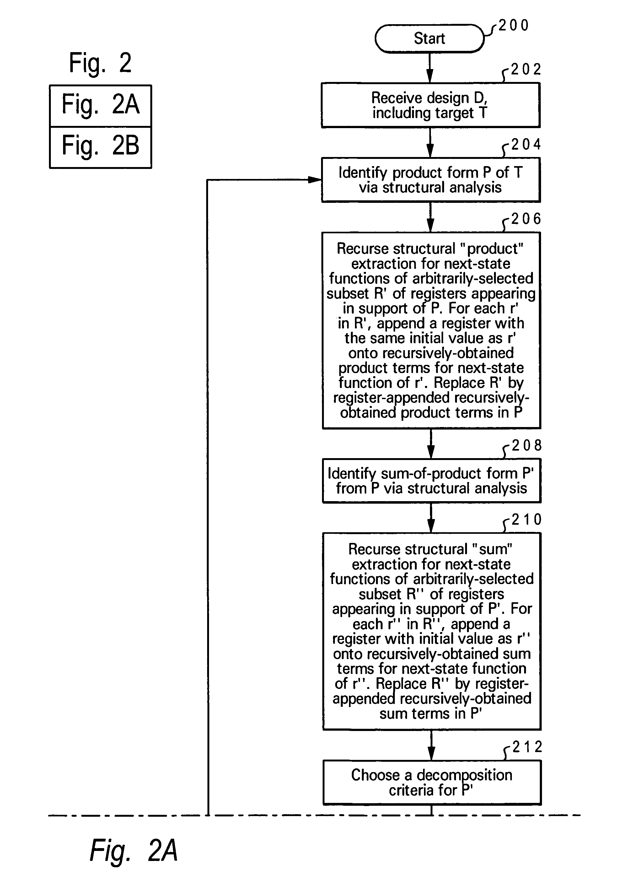
[0018]The present invention provides a method, system, and computer program product for enhanced verification through structural target decomposition. As will be explained below, a preferred embodiment of the present invention provides a novel method for reducing verification complexity via decomposing targets into simpler sub-targets which may be independently verified. The approach of the present invention is useful both for completing proofs, as well as for finding counterexamples. The approach of the present invention is also particularly useful in combination with other transformation algorithms, possibly as a component of a transformation-based verification system.

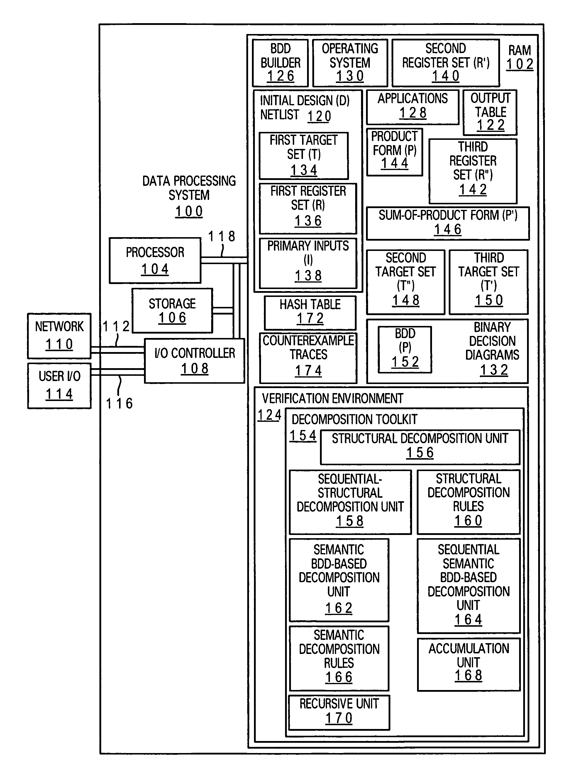
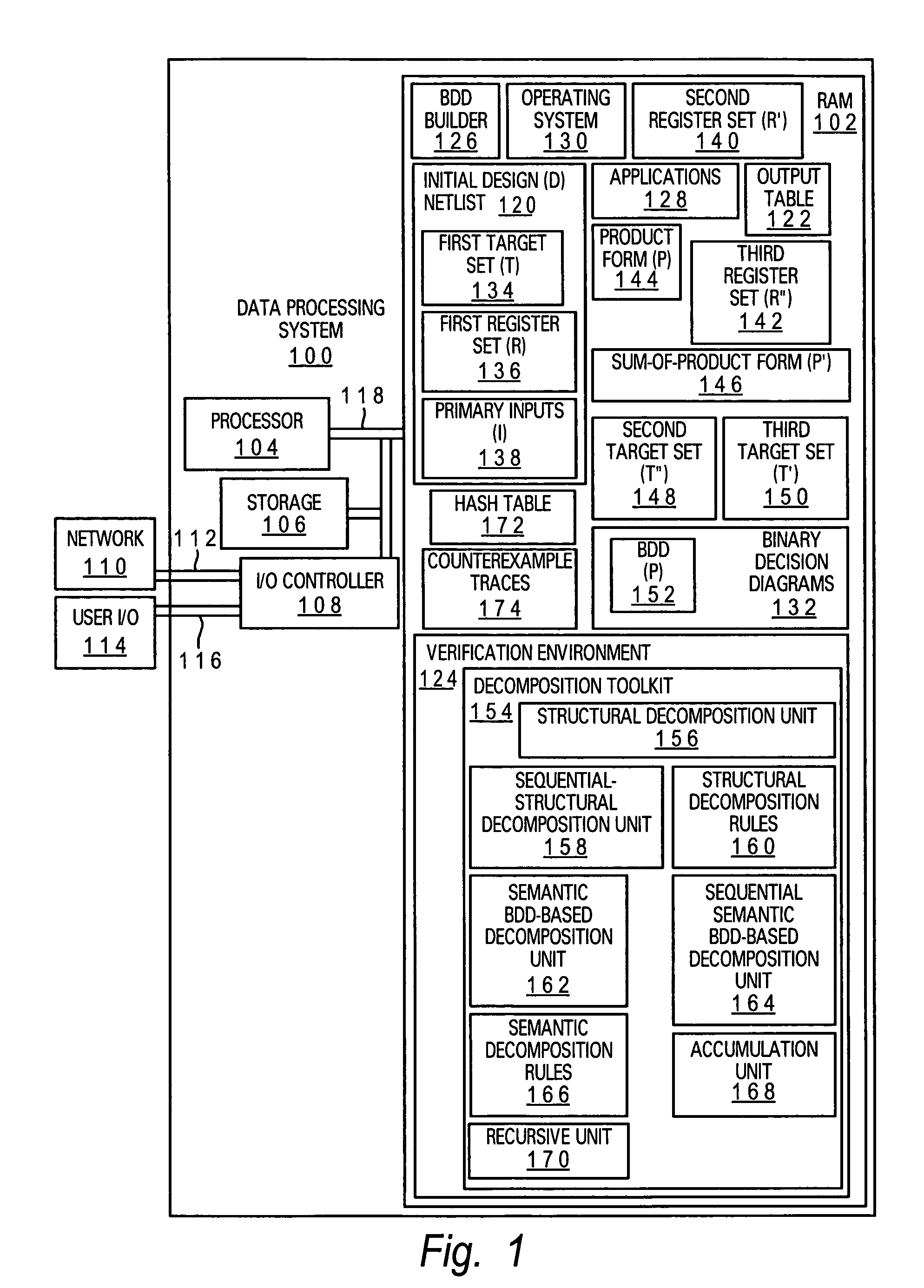
[0019]With reference now to the figures, and in particular with reference to FIG. 1, a block diagram of a general-purpose data processing system for performing the present invention of a method, system and computer program product enhanced verification through structural target decomposition, is depicted. Data proces...


PUM


Abstract

A method, system and computer program product for performing verification of an electronic design is disclosed. The method includes receiving a design, wherein the design includes a first target set and a first register set including one or more registers. A structural product extraction is formed from one or more targets from the first target set and the structural product extraction is recursed for one or more next-state functions of a subset of the one or more registers. A sum-of-products form is recursed from the structural product extraction for one or more next-state functions of a subset of the one or more registers and a product-of-sums form of a result of the second recursing is decomposed to generate a decomposition of the product-of-sums form. The decomposition of the product-of-sums form is synthesized into a second target set and a subset of the second target set to recursively decompose is chosen. In response to the subset of the second target set being nonempty, the first target set is recursively decomposed and, in response to the second target set being empty, verification is applied to the second target set.

Description

CROSS-REFERENCE TO RELATED APPLICATIONS[0001]The present application is related to the following co-pending U.S. patent applications filed on even date herewith, and incorporated herein by reference in their entirety:[0002]Ser. No. 11,143,331(AUS 920050371US 1), entitled “METHOD AND SYSTEM FOR ENHANCED VERIFICATION THROUGH BINARY DECISION DIAGRAM-BASED TARGET DECOMPOSITION”.BACKGROUND OF THE INVENTION[0003]1. Technical Field[0004]The present invention relates in general to verifying designs and in particular to decomposing logic. Still more particularly, the present invention relates to a system, method and computer program product for performing structural target decomposition.[0005]2. Description of the Related Art[0006]With the increasing penetration of processor-based systems into every facet of human activity, demands have increased on the processor and application-specific integrated circuit (ASIC) development and production community to produce systems that are free from desi...

Claims


Application Information

Patent Timeline
Patent Type & Authority Patents(United States)
IPC IPC(8): G06F17/50
CPCG06F17/504G06F17/5045G06F30/3323G06F30/30
Inventor BAUMGARTNER, JASON RAYMONDKANZELMAN, ROBERT LOWELLMONY, HARIPARUTHI, VIRESH
Owner GOOGLE LLC
Why Eureka
Try Eureka