Cylinder unit for mounting on a cross member and/or a table of a device or machine for the deformation of workpieces

a technology of workpiece deformation and cylinder unit, which is applied in the direction of mechanical equipment, liquid fuel engines, press rams, etc., can solve the problems of easy misalignment of the guide system of the unit, the impression of the piston all the way into the workpiece, etc., and achieve the effect of easy compensation of the length change of the cylinder block

Inactive Publication Date: 2008-04-01
THEODOR GRABENER
View PDF6 Cites 0 Cited by
  • Summary
  • Abstract
  • Description
  • Claims
  • Application Information

AI Technical Summary

Benefits of technology

[0006]Therefore, it is the primary object of the present invention to provide a cylinder unit in which the pistons do not produce any imprints on the workpiece, and in which the length changes of the cylinder block can be compensated very easily.
[0008]The cylinder unit according to the present invention has the particular advantage that each pressure piece, which is supported by the spherically shaped head of a piston and has a recess corresponding to the spherically shaped head, does not cause imprints or bulges on the deformed workpiece. In addition, the load is uniformly distributed over the workpiece.

Problems solved by technology

This arrangement has the disadvantage that imprints of the pistons can be seen all the way into the workpiece.
Another disadvantage of the known cylinder units is to be seen in the fact that the guide systems of the units become easily misaligned because the cylinder block expands when it is heated by the hydraulic oil which actuates the pistons.

Method used


Image

  • Cylinder unit for mounting on a cross member and/or a table of a device or machine for the deformation of workpieces
  • Cylinder unit for mounting on a cross member and/or a table of a device or machine for the deformation of workpieces
  • Cylinder unit for mounting on a cross member and/or a table of a device or machine for the deformation of workpieces

Examples


Embodiment Construction

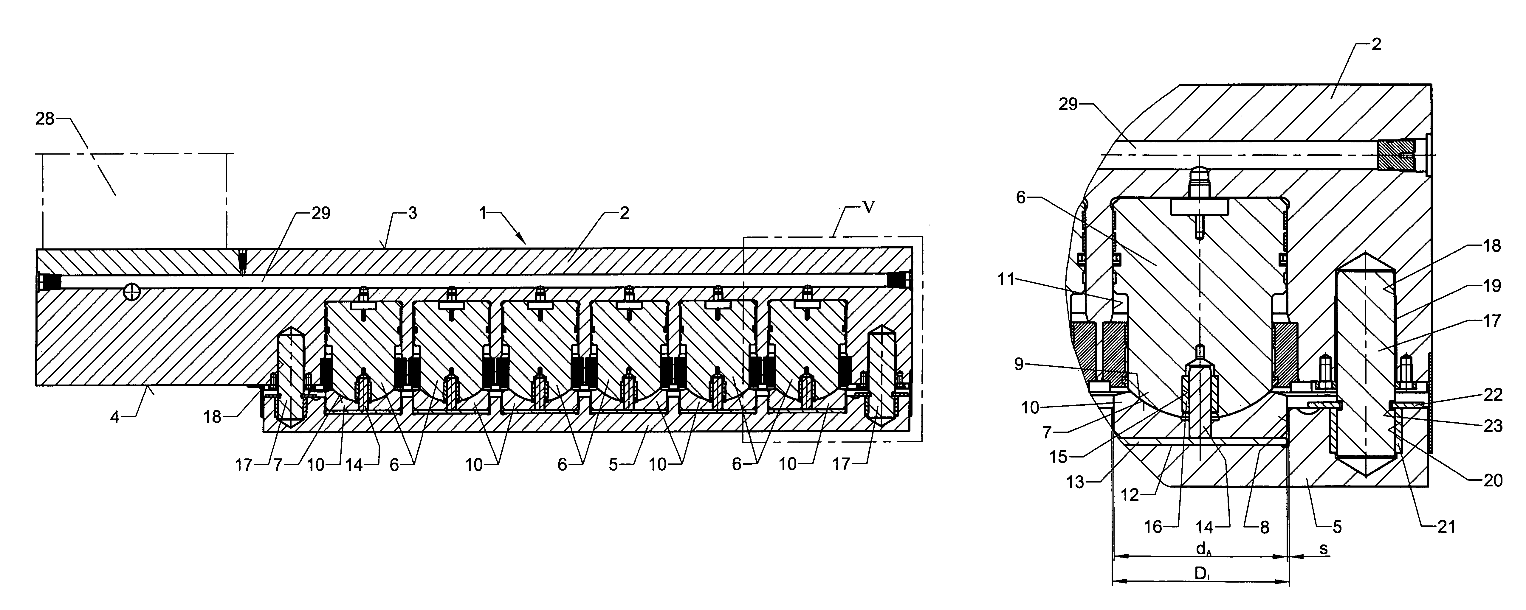
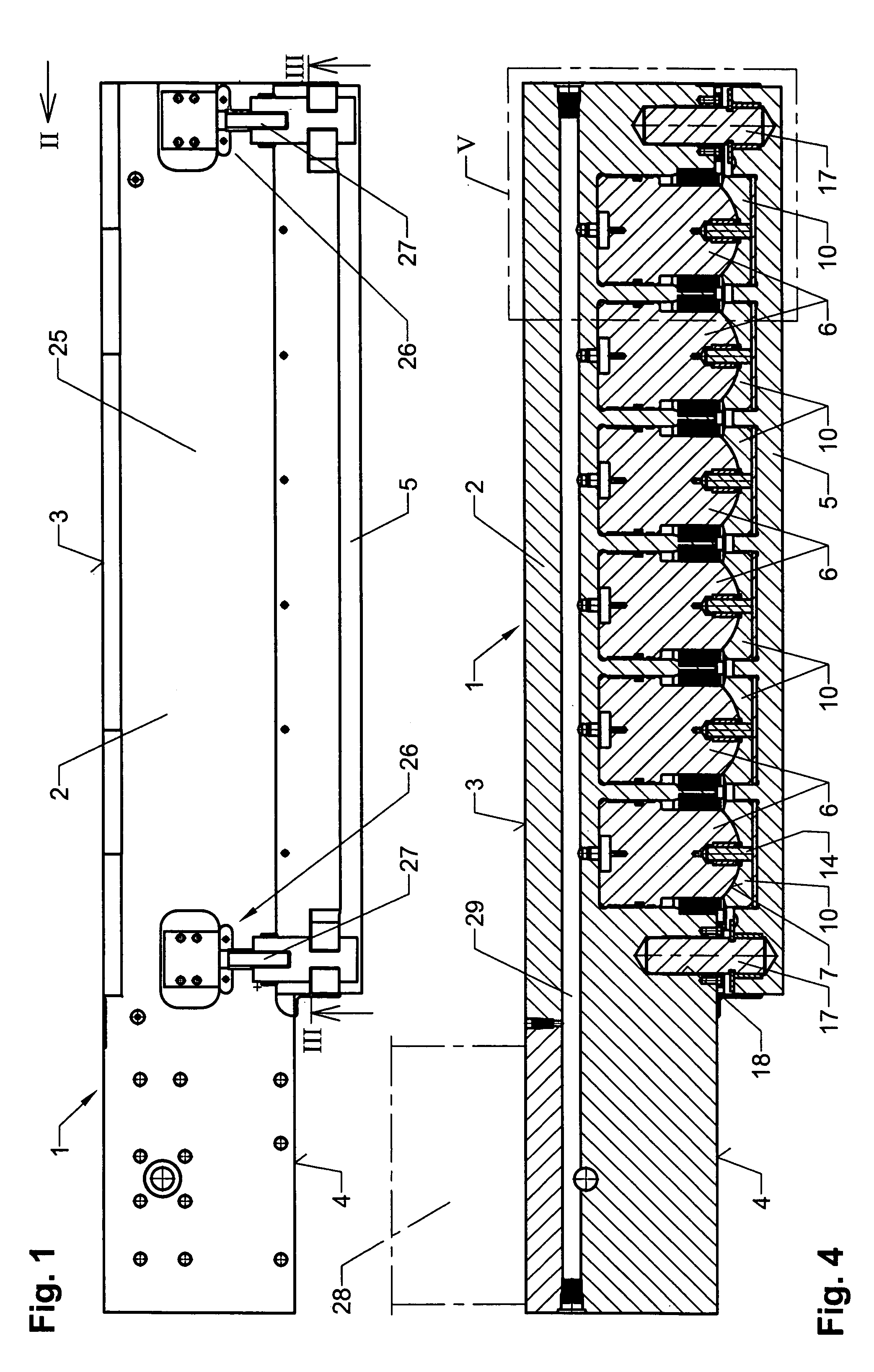
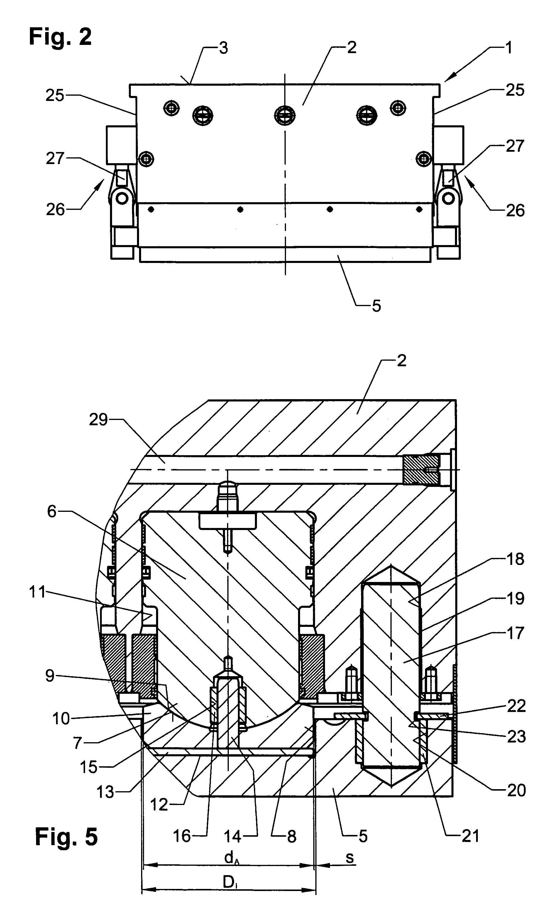
[0017]The cylinder unit 1 illustrated in the drawing is intended for mounting on a crossmember and / or a table of a device or machine for deforming workpieces, not shown. The cylinder unit 1 is composed of a cylinder block 2 which can be mounted on the cross member and / or the table, and a pressure plate 5 mounted on a surface 4 of the cylinder block 2 facing away from the mounting surface 3. A plurality of pistons 6 each having a spherically shaped head 7 is mounted in the cylinder block 2, wherein the pistons 6 jointly act on the pressure plate 5.

[0018]Mounted on the spherically shaped head 7 of each piston 6 is a pressure piece 10 which protrudes into a bore 8 of the pressure plate 5 and is provided with a recess 9 which corresponds to the spherically shaped head 7. As particularly seen in FIG. 5, a gap s is provided between the outer diameter dA of each pressure piece 10 and the inner diameter di of the bore 8, so that a length expansion due to heat does not result in a misalignme...


PUM


Abstract

A cylinder unit for mounting on a machine for the deformation of workpieces includes a cylinder block and a pressure plate which is arranged on the surface of the cylinder block which faces away from the fastening surface, wherein a plurality of pistons each having a spherically shaped head are mounted in the cylinder block. Mounted on each spherically shaped head of the pistons is a pressure piece which protrudes into a bore of the pressure plate and has a recess corresponding to the spherically shaped head of the pistons. A gap is provided between the outer diameter of the pressure piece and the inner diameter of the bore in the pressure plate. A pressure disc is arranged between the pressure piece and the pressure plate in the bottom of the bore of the pressure plate. Each pressure piece includes a coaxial guide pin which protrudes beyond the pressure piece in the direction of the piston, wherein the guide pin projects into a coaxial bore in the spherically shaped head of the piston, and wherein an elastic guide sleeve is provided in the coaxial bore between the guide pin and the coaxial bore.

Description

BACKGROUND OF THE INVENTION[0001]1. Field of the Invention[0002]The present invention relates to a cylinder unit for mounting on a cross member and / or a table of a device or machine for the deformation of workpieces. The cylinder unit includes a cylinder block which can be mounted on the cross member and / or at the table and a pressure plate which is arranged on the surface of the cylinder block which faces away from the fastening surface, wherein a plurality of pistons each having a spherically shaped head are mounted in the cylinder block, wherein the pistons act on the pressure plate, and wherein guide bolts are arranged in the pressure plate which protrude into the cylinder block and are guided in the cylinder block.[0003]2. Description of the Related Art[0004]Cylinder units of the above-described type are known in the art. In these units, the spherically shaped heads of the pistons act directly on a pressure piece having a flat surface which is mounted in the pressure plate. Thi...

Claims


Application Information

Patent Timeline
Patent Type & Authority Patents(United States)
IPC IPC(8): F01B1/00B30B1/34B30B15/06F15B15/14
CPCB30B1/34B30B15/068F15B15/1404F15B15/1471
Inventor KAPP, DIETER
Owner THEODOR GRABENER
Why Eureka
Try Eureka