Surrounding strip press-fit feeding machine

A feeder and apron technology, which is applied in the direction of sending objects, thin material processing, and gluing shoe parts, etc., can solve the problems of large changes in the extrusion force of the apron, large error in affixing the apron, and affecting the quality of the affixation, and achieves Avoid drastic changes, avoid slack state, and improve the effect of attaching quality

Pending Publication Date: 2018-08-24
QUANZHOU HUAZHONG UNIV OF SCI & TECH INST OF MFG
View PDF8 Cites 0 Cited by
  • Summary
  • Abstract
  • Description
  • Claims
  • Application Information

AI Technical Summary

Problems solved by technology

[0003] Existing vulcanized shoes usually use manual bonding to complete the process of attaching the perimeter strips, and the perimeter strips need to be cut and glued between the fittings, because the waste generated by cutting may not adhere to the cut strips. On the fence, it needs to be cleaned before use to apply glue, and the production efficiency is relatively low
[0004] There are also some enterprises that use equipment such as manipulators to realize the automatic attachment of the fences. Although the production efficiency can be improved, the quality of the attachment is relatively low. Attachment track, the attachment track is also the shape of the enclosure attached to the vulcanized shoe, the shape is as figure 1 As shown, it is a closed-loop and irregular shape formed by the connection of multiple curves. The radius of curvature at the position corresponding to the toe and heel is relatively small, while the radius of the crank at the position corresponding to the waist is relatively large. Therefore, if Directly use the scanning device to rotate around the vulcanized shoe and obtain the attachment track for the handover position between the upper and the sole, then the attachment track will be due to the distance between two adjacent phase acquisition points of the industrial camera of the scanning device There is a difference between the actual attachment trajectory and the actual attachment trajectory. Specifically, the attachment trajectory acquired by the scanning device will shrink inwards relative to the actual attachment trajectory at the position corresponding to the toe and heel. In addition, the scanning device will In the process of forming the attachment trajectory through fitting processing, in order to ensure the smoothness of the trajectory, it is inevitable to perform interpolation filtering, and the above-mentioned shrinkage phenomenon may also occur. The existence of the shrinkage phenomenon makes the manipulator use the attachment trajectory obtained by the scanning device to stick During the process of attaching the surrounding strip, the extrusion force on the surrounding strip changes relatively greatly, which makes the surrounding strip deformed, and the error of the surrounding strip is relatively large, which affects the quality of the attachment

Method used


Image

  • Surrounding strip press-fit feeding machine
  • Surrounding strip press-fit feeding machine
  • Surrounding strip press-fit feeding machine

Examples


Embodiment Construction

[0033] The present invention will be further described below in conjunction with the accompanying drawings and specific embodiments.

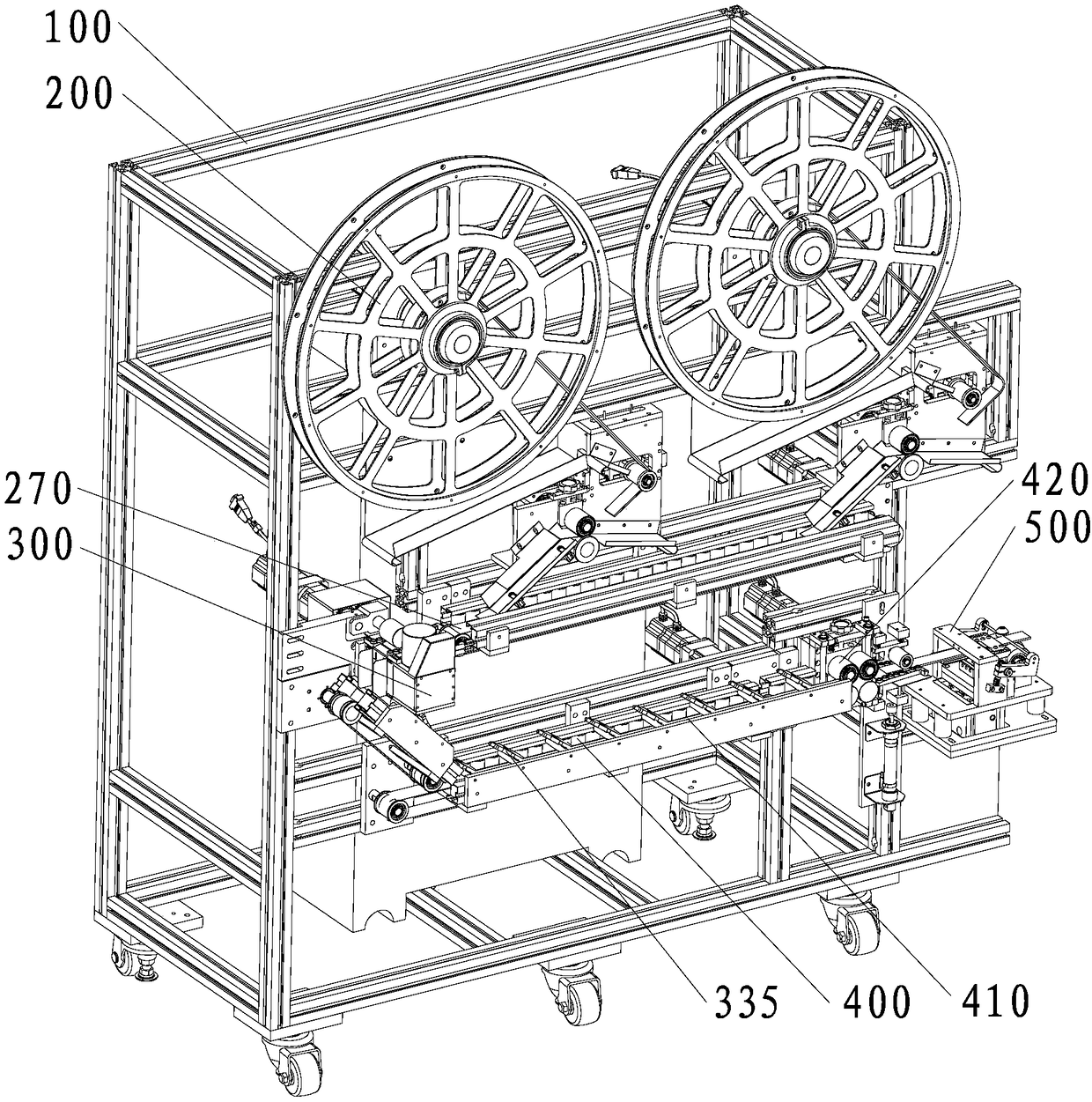
[0034] Such as figure 2 As shown, the bar pressing and feeding machine provided in this embodiment includes a frame 100, an unwinding device 200, a gluing device 300, a drying device 400 and a pressing device 500 are arranged on the frame 100, wherein the unwinding The device 200 is located above the drying device 400, and the gluing device 300 and the pressing device 500 are respectively located on both sides of the drying device 400. Of course, the enclosure pressing and feeding machine provided in this embodiment should also include a control device for communicating with each device. system, the control system can be a conventional system, which can be directly purchased from the market and set according to actual functional requirements, which is not the focus of this embodiment and will not be described in detail here.

[0035] When in ...


PUM


Abstract

The invention provides a surrounding strip press-fit feeding machine. The surrounding strip press-fit feeding machine comprises a rack, and the rack is provided with an unreeling device, a gluing device, a drying device and a press-fit device. The press-fit device comprises a tensioning assembly and an attaching assembly which are sequentially arranged. The attaching assembly comprises a supporting plate, a movable base, a supporting spring, a supporting shaft, a carrier roller, a guide rod, a needle-shaped air cylinder, a limiting wheel, a swinging rod, a pressing rod, a reset spring and an elevating air cylinder. The reset spring and the elevating air cylinder are located at the positions corresponding to the two ends of the swinging rod correspondingly. One end of the reset spring abutsagainst the movable base, and the other end of the reset spring abuts against the swinging rod. The side, towards the tensioning assembly, of the carrier roller is provided with a shearing mechanism.The supporting spring is utilized for compensating for the contraction amount existing in the scanning track, in the surrounding strip attaching process, the changes of extrusion force exerted on thesurrounding strip are relatively weak, the surrounding strip is not prone to deformation, the attaching error is small, the production efficiency is relatively high, and the attaching quality is relatively good.

Description

technical field [0001] The invention relates to a production equipment for vulcanized shoes, in particular to a strip pressing and feeding machine. Background technique [0002] Vulcanized shoes are a kind of shoes formed by using rubber, fabric or leather as the upper surface, using rubber as the bottom material to be processed by pasting, molding or injection, and then vulcanized under a certain temperature and pressure. The sole of vulcanized shoes There is usually an apron attached between the upper and the upper, which is used to strengthen the strength of the shoe and make the appearance more beautiful. [0003] Existing vulcanized shoes usually use manual bonding to complete the process of attaching the perimeter strips, and the perimeter strips need to be cut and glued between the fittings, because the waste generated by cutting may not adhere to the cut strips. On the fence, it needs to be cleaned before use to apply glue, and the production efficiency is relativel...

Claims


Application Information

Patent Timeline
Patent Type & Authority Applications(China)
IPC IPC(8): B65H37/04A43D25/08
CPCA43D25/08B65H37/04B65H2701/11332
Inventor 张明全李文亮苏惠阳张鸿翔冯少平王平江
Owner QUANZHOU HUAZHONG UNIV OF SCI & TECH INST OF MFG
Why Eureka
Try Eureka