Ball feeder for ball serving machine

a technology of serving machine and feeder, which is applied in the direction of ammunition loading, sports equipment, weapons, etc., can solve the problems of inconvenient assembly and transportation, complicated structure of feeder, and difficulty in packaging and transportation, so as to facilitate easy guiding of balls and reduce space

Inactive Publication Date: 2008-04-01
LONG WAY ENTERPRISE
View PDF10 Cites 20 Cited by
  • Summary
  • Abstract
  • Description
  • Claims
  • Application Information

AI Technical Summary

Benefits of technology

[0005]A primary object of the present invention is to provide a ball feeder for ball serving machine in which a plurality of foldable guide sections may be developed into a spiral ball guide path that facilitates easy guiding of balls to the ball serving machine and occupies a reduced space.
[0006]Another object of the present invention is to provide a ball feeder for ball serving machine that includes a plurality of easily foldable guide sections to largely reduce the volume and weight of the ball feeder and accordingly enable easy storage and transport of the ball feeder.
[0008]A still further object of the present invention is to provide a ball feeder for ball serving machine that includes a rotating unit to control the rotating speed of a ball scoop, so that a ball fallen onto the ball scoop is fed to the ball serving machine at a controlled speed to facilitate good control of a serving rate of the ball serving machine.

Problems solved by technology

Most of the conventional ball feeders for use with the ball serving machine include a metal-made long ball path, and a motor and an elastic wheel to drive the balls forward, and are therefore bulky and heavy to cause difficulties in packaging and transporting them.
Balls driven to move forward by the motor and the elastic wheel in the conventional ball feeder tend to skid or be stuck in the ball path.
Moreover, the conventional ball feeders usually have complicate structure and are inconvenient to assemble and transport, and require considerably large space for storage.

Method used


Image

  • Ball feeder for ball serving machine
  • Ball feeder for ball serving machine
  • Ball feeder for ball serving machine

Examples


Embodiment Construction

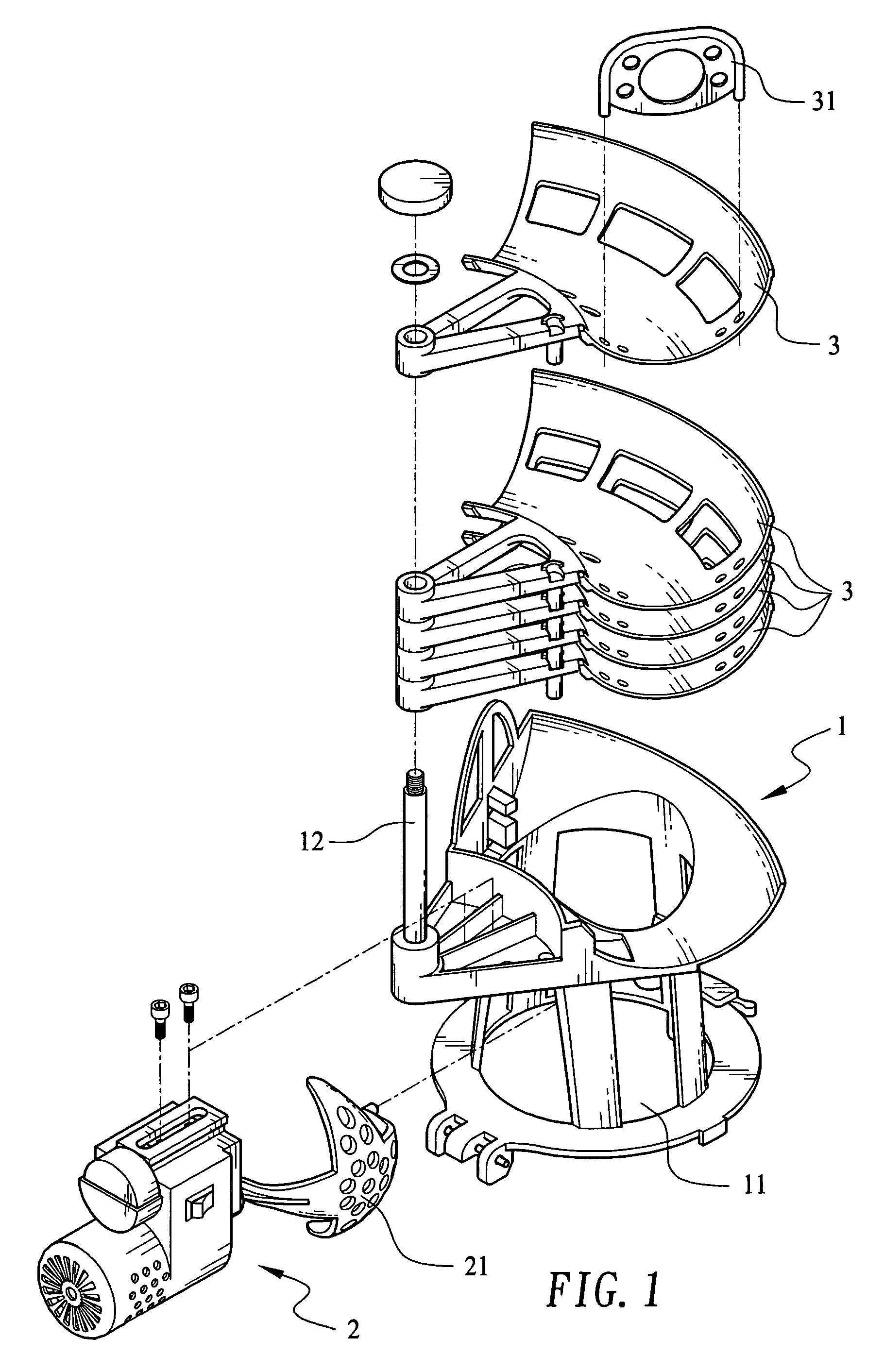
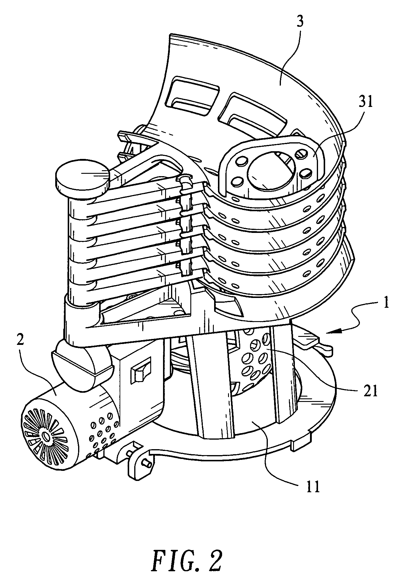
[0019]Please refer to FIGS. 1 and 2 that are exploded and assembled perspective views, respectively, of a ball feeder for ball serving machine according to a preferred embodiment of the present invention.

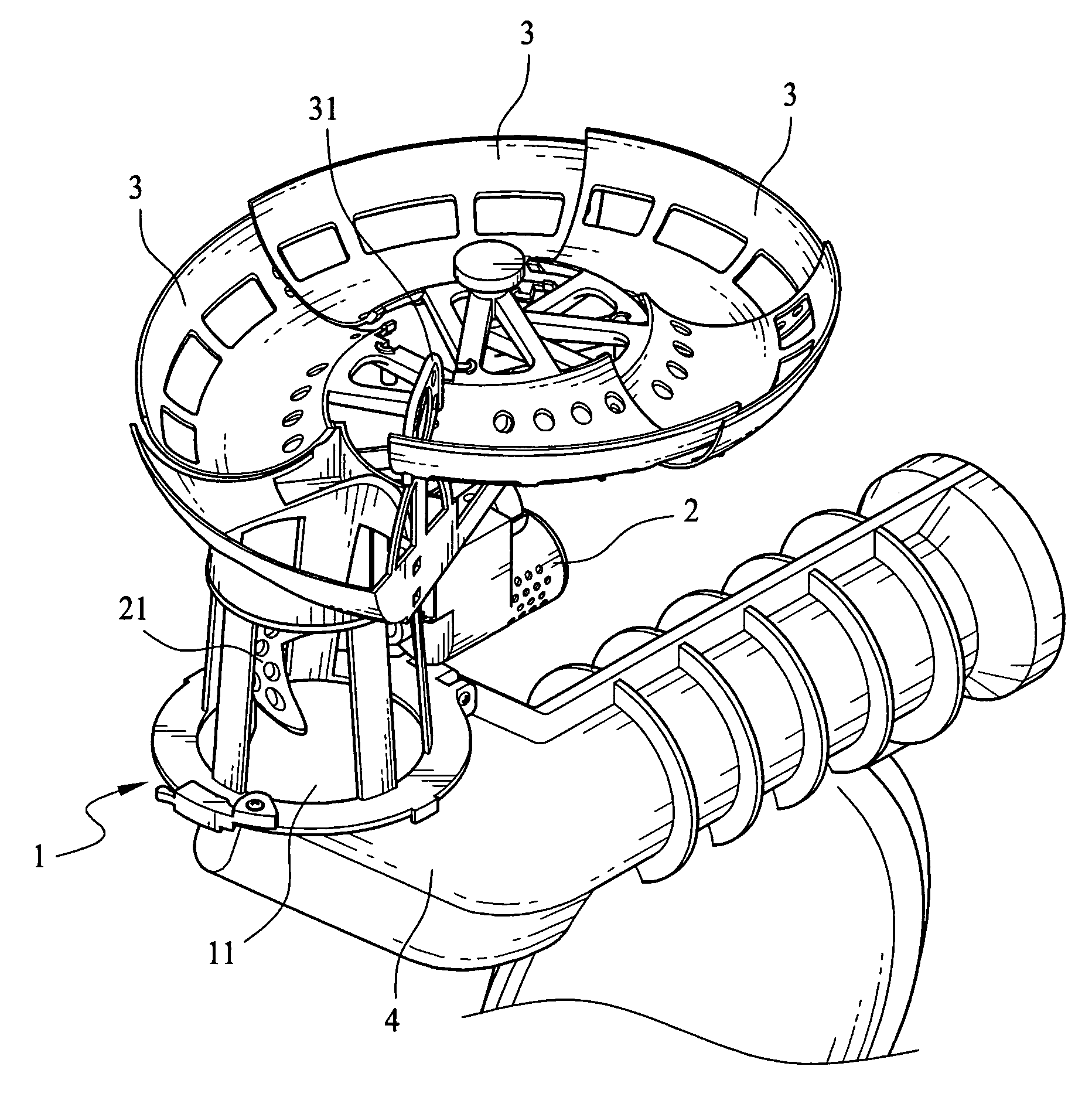
[0020]As shown, the ball feeder for ball serving machine according to the present invention includes a seat 1 consisting of a hollow transfer frame 11 and a shaft bearing 12; a rotating unit 2 mounted to one side of the seat 1 and having a ball scoop 21 extended from an end of the rotating unit 2; and a plurality of guide sections 3 sequentially rotatably connected at an end to the shaft bearing 12 for forming a ball guide path.

[0021]The ball scoop 21 extended from the rotating unit 2 is located in the hollow transfer frame 11 of the seat 1 to contact with an inner wall surface of the transfer frame 11. The rotating unit 2 is a motor or an electromagnetic valve for controlling a rotating speed of the ball scoop 21. A stopper 31 is movably connected to an outer end of a top guide sec...


PUM


Abstract

A ball feeder for ball serving machine includes a seat consisting of a hollow transfer frame and a shaft bear, a rotating unit mounted to one side of the seat and having a ball scoop extended from an end thereof, and a plurality of guide sections sequentially rotatably connected at an end to the shaft bearing. The guide sections may be turned about the shaft bearing in the same direction to form a nonlinearly inclined spiral ball guide path. A ball put in the top guide section automatically rolls down along the ball guide path and falls into the transfer frame to be caught by the ball scoop. When the ball scoop is turned by the rotating unit to face downward, the ball on the ball scoop falls into a feeding mouth on a body of the ball serving machine and is automatically served.

Description

FIELD OF THE INVENTION[0001]The present invention relates to a ball feeder for ball serving machine, and more particularly to a ball feeder for ball serving machine in which a plurality of guide sections may be developed from a folded state into a spiral ball guide path, along which a ball is sent to a feeding mouth on the ball serving machine and automatically served. With the foldable guide sections, the ball feeder may have reduced volume for easy storage and transport.BACKGROUND OF THE INVENTION[0002]Various kinds of products in connection with ball games, including baseball, table tennis, tennis, etc., have been developed and are available in the market. Most of the ball games require special sporting equipment, place, and fixed number of players. Thus, many ball-game players and lovers have to use practicing instruments to develop their skill. A ball serving machine is one example of such practicing instruments. With the ball serving machine, ball-game players and lovers may t...

Claims


Application Information

Patent Timeline
Patent Type & Authority Patents(United States)
IPC IPC(8): F41B4/00A63B47/00A63B69/40
CPCA63B47/002A63B69/40A63B2047/004
Inventor YAO, LIN ZHANLI, ZE JUN
Owner LONG WAY ENTERPRISE
Why Eureka
Try Eureka