
Light guide plate of LED backlight unit

a technology of led backlight unit and light guide plate, which is applied in waveguides, lighting and heating apparatus, instruments, etc., can solve the problems of increased frequency of defective light guide plate, difficult molding operation, and difficulty in mold production, so as to facilitate mold production and easy and stable production of light guide plate

Active Publication Date: 2008-04-01
SAMSUNG ELECTRONICS CO LTD
View PDF3 Cites 13 Cited by
  • Summary
  • Abstract
  • Description
  • Claims
  • Application Information

AI Technical Summary

Benefits of technology

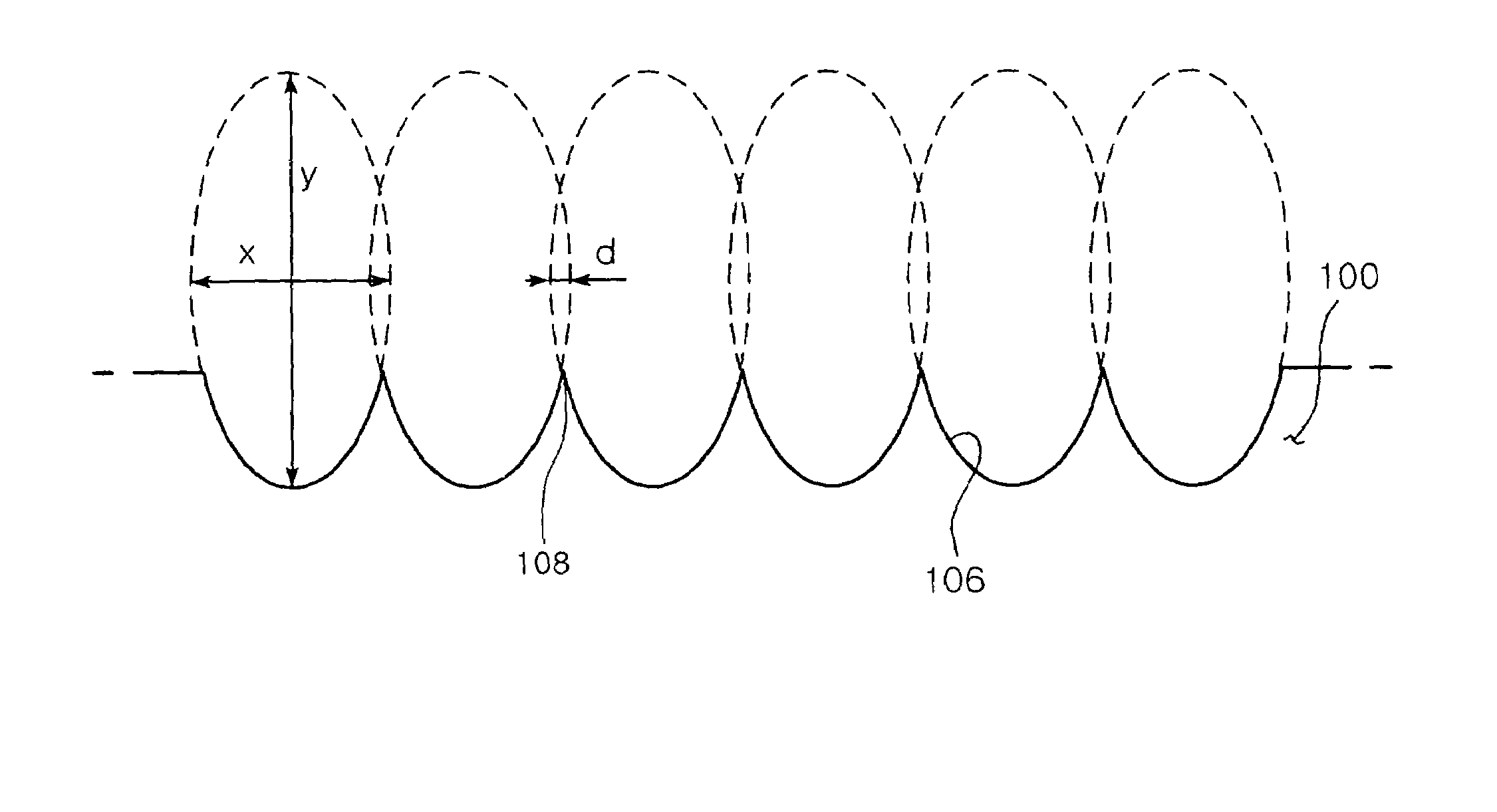
The present invention provides a light guide plate for an LED backlight unit that has elliptic cylinder-shaped grooves on its incident plane to widen the incidence angle of light transmission. The grooves are formed on the narrow plane of the light guide plate, which faces the LED light source, and a pinnacle is formed between the grooves. The wide plane of the light guide plate acts as the exiting plane from which the light enters. The carved elliptic cylinder-shaped grooves extend in a thickness direction of the exiting plane, and each overlapping portion between the ellipses forms a pinnacle extending outward from the incident plane. The technical effects of the invention include improved light transmission and stable production of the light guide plate using the mold.

Problems solved by technology

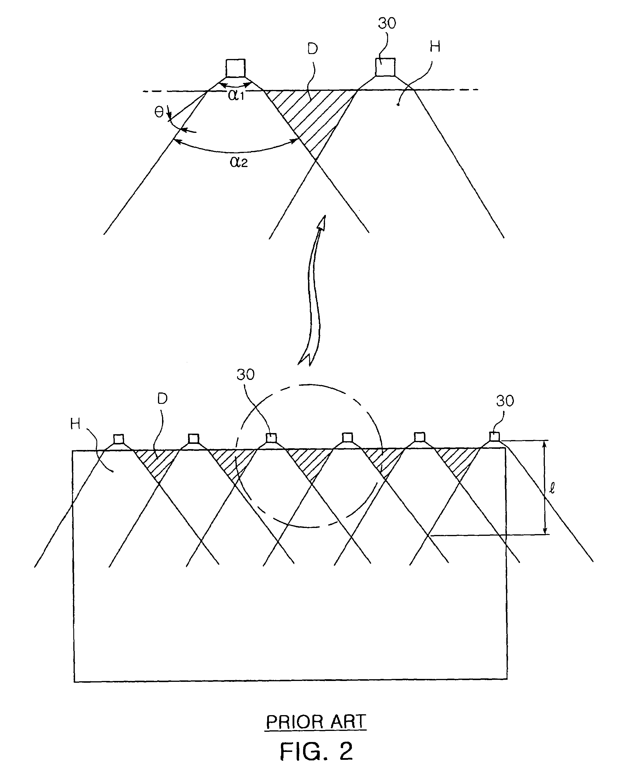
However, the configurations of FIGS. 4 and 5 suffer from problems as follows.
Moreover, the light guide plate is likely to be broken at a portion thereof due to an impact upon separation, which increases frequency of defective light guide plates.
That is, since the protrusions 52 are formed on the inner surface of the mold 50 for molding the light guide plates 20A and 20B, the conventional light guide plate causes difficulty in molding operation, and suffers from defective molding.

Method used


Image

  • Light guide plate of LED backlight unit
  • Light guide plate of LED backlight unit
  • Light guide plate of LED backlight unit

Examples


Embodiment Construction

[0044]Preferred embodiments will now be described in detail with reference to the accompanying drawings.

[0045]FIG. 7 is a plan view showing an incident plane of a light guide plate according to the invention, and FIG. 8 is a perspective view of the light guide plate shown in FIG. 7.

[0046]Referring to FIGS. 7 and 8, a light guide plate 100 is used for a backlight unit having an LED light source, and has substantially the same arrangement as that shown in FIG. 1.

[0047]The light guide plate 100 has a planar shape, and is made from a transparent glass, plastic acryl, or PMMA (polymethylmethacrylate).

[0048]The light guide plate 100 comprises a pair of wide planes, that is, upper and lower surfaces 102, facing each other, and narrow planes, that is, side surfaces 104, formed between the wide planes 102 and constituting a thickness of the light guide plate. One of the narrow planes facing the LED light source 130, that is, one narrow plane at a leading end 100a of the light guide plate 100...


PUM


Abstract

A light guide plate of an LED backlight unit is disclosed. The light guide plate comprises a pair of wide planes facing each other, and a narrow plane formed between the pair of wide planes and constituting a thickness of the light guide plate. The narrow plane has an incident plane formed on a section of the narrow plane facing the LED light source, and one of the wide planes constitutes an exiting plane from which light entered from the LED light source exits. The incident plane has a plurality of elliptic cylinder-shaped grooves carved into the incident plane in a thickness direction of the light guide plate. As such, the elliptic cylinder-shaped grooves are carved into the incident plane of the light guide plate in the thickness direction, widening an incidence angle of which light can be transmitted therethrough.

Description

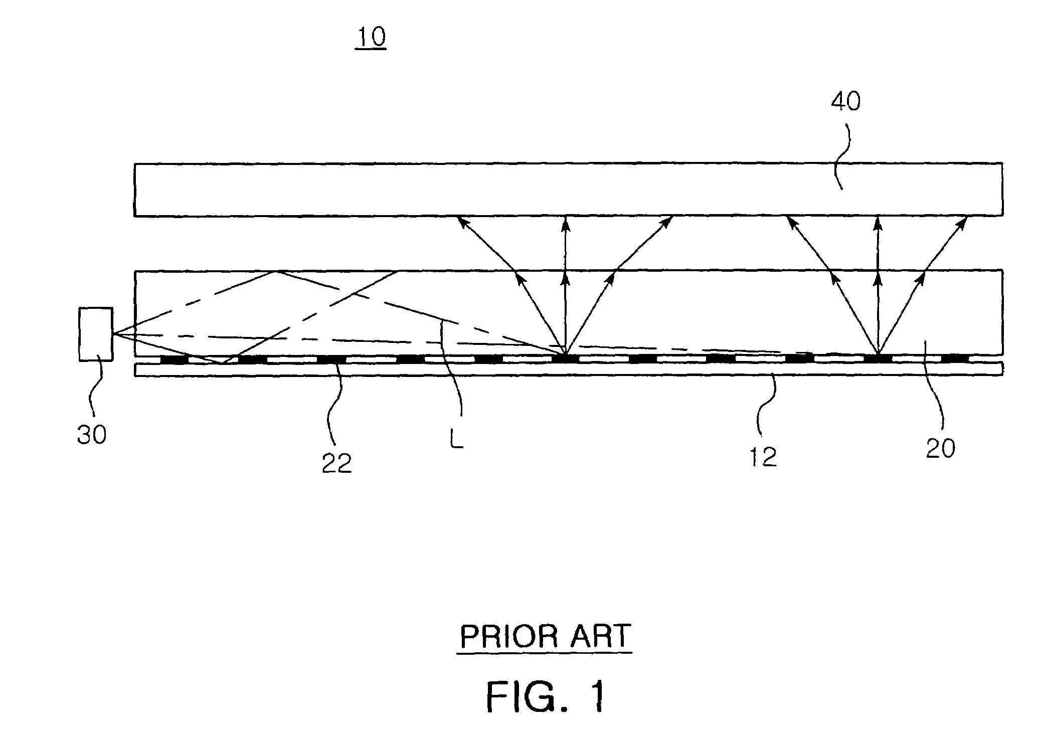
CLAIM OF PRIORITY[0001]The present invention is based on, and claims priority from, Korean Application Number 2005-112541, filed Nov. 23, 2005, the disclosure of which is incorporated by reference herein in its entirety.BACKGROUND OF THE INVENTION[0002]1. Field of the Invention[0003]The present invention relates to a light guide plate of a light emitting device (LED) backlight unit, and, more particularly, to a light guide plate of an LED backlight unit, which has a plurality of elliptic cylinder-shaped grooves carved into an incident plane of the light guide plate in a thickness direction to widen an incidence angle of which light can be transmitted therethrough.[0004]2. Description of the Related Art[0005]A small light crystal display (LCD) for mobile phones and personal digital assistants (PDA) generally employs a lateral light emitting diode (LED) as a light source of a backlight unit. Such a lateral LED is generally provided to the backlight unit as shown in FIG. 1.[0006]Referr...

Claims


Application Information

Patent Timeline
Patent Type & Authority Patents(United States)
IPC IPC(8): F21V7/04
CPCG02B6/0016G02B6/0068Y10S385/901G02F1/1335
Inventor YANG, SUNG MIN
Owner SAMSUNG ELECTRONICS CO LTD
Learn More