
Method and apparatus for salvaging underwater pipelines

Active Publication Date: 2008-04-01
KELLY JOHN M +1
View PDF18 Cites 43 Cited by
  • Summary
  • Abstract
  • Description
  • Claims
  • Application Information

AI Technical Summary

Benefits of technology

[0016]The moving blade travels in opposed slots on the frame. Rails prevent the moving blade from deflecting laterally as it travels upon a selected guided path.
[0017]The two guides or rails also prevent deflection of the fixed blade.

Problems solved by technology

In the offshore oil and gas industry and in other marine environments, there are a number of old, damaged or abandoned pipelines or sections of pipe that scatter the seabed.
At times, catastrophic events such as hurricanes damage pipelines beyond repair so that they must be removed from the seabed with a salvage operation.
Pipelines can be scattered over miles and in very deep water making salvage operations difficult and expensive.

Method used


Image

  • Method and apparatus for salvaging underwater pipelines
  • Method and apparatus for salvaging underwater pipelines
  • Method and apparatus for salvaging underwater pipelines

Examples


Embodiment Construction

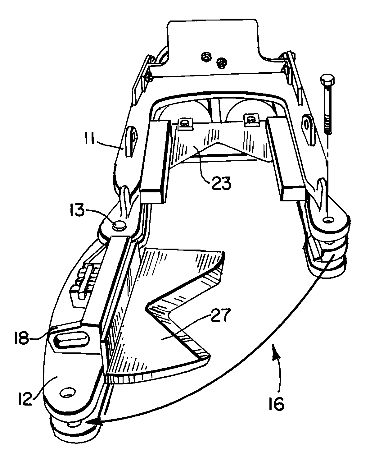
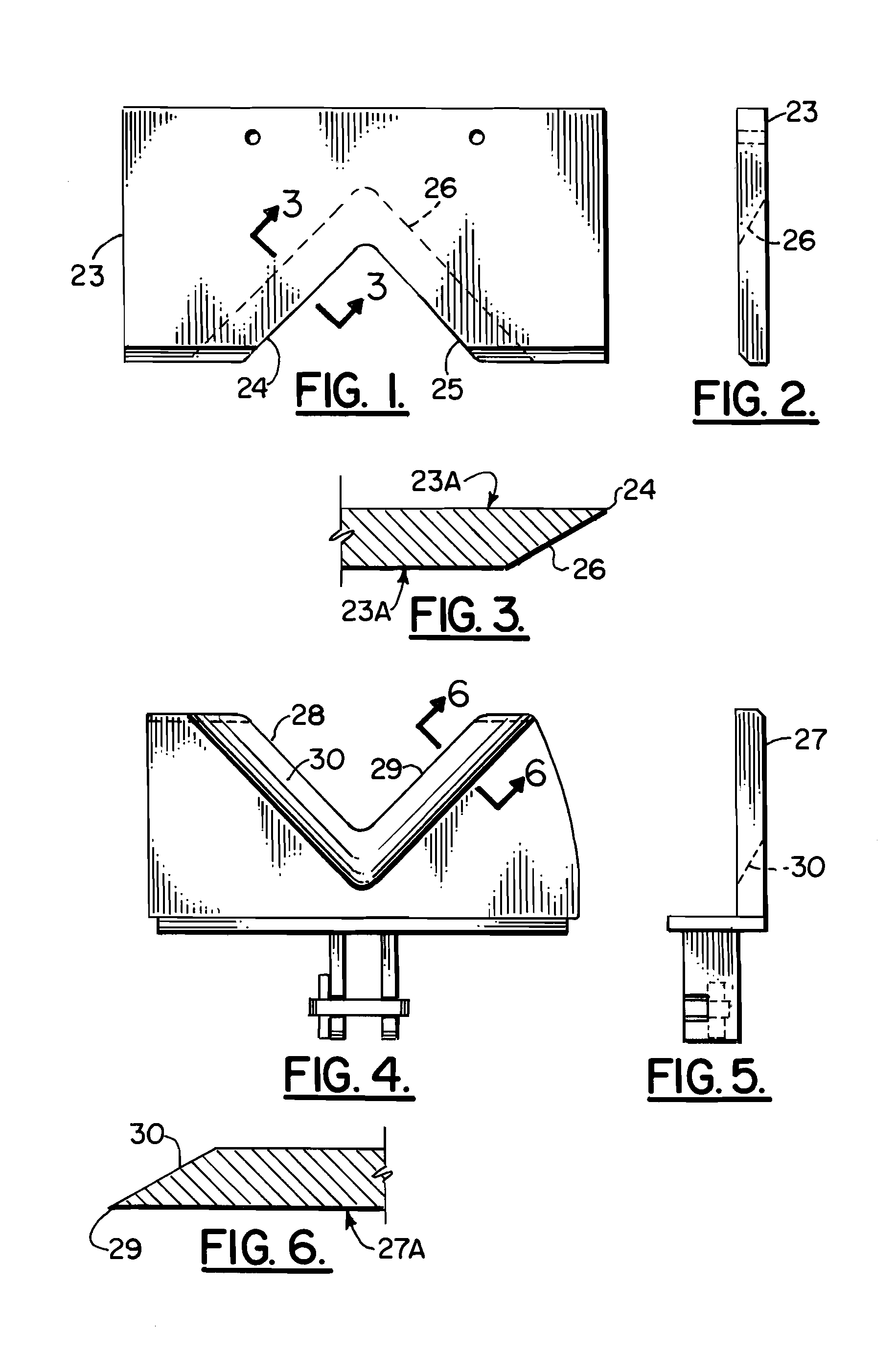
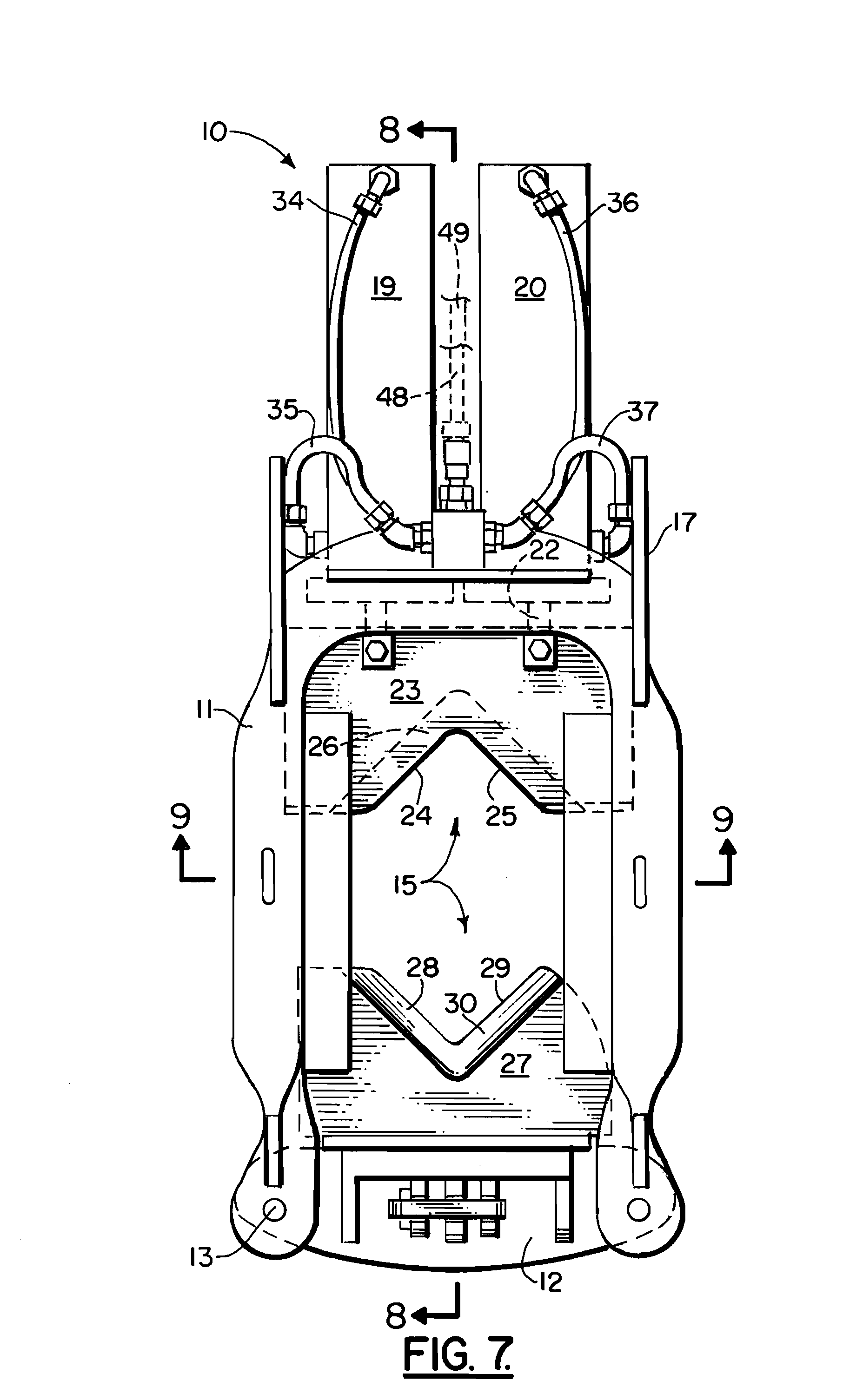
[0036]FIGS. 1-12 show generally the preferred embodiment of the apparatus of the present invention, wherein it is designated generally by the numeral 10. Pipe or pipe section cutting apparatus 10 provides a frame 11 to which is pivotally attached a gate 12. It should be understood that the apparatus 10 of the present invention can be used to cut material other than cylindrical pipe, such as tubing or piling (e.g. steel, wood, reinforced concrete or of composite construction).

[0037]Hinge 13 forms a pivoting connection between frame 11 and gate 12. Gate 12 can be closed and secured in the closed position with pinned connection 14. When the gate 12 is in a closed position (see FIG. 7), an open center 15 is provided, that being an area that is occupied by the pipeline to be cut during use. The apparatus 10 thus provides an open end portion 16 and a closed end portion 17. The gate 12 can be provided with a handle 18 that enables a user (e.g. diver) to open and close the gate 12 with resp...


PUM

PropertyMeasurementUnit
Angleaaaaaaaaaa
Angleaaaaaaaaaa
Sizeaaaaaaaaaa

Abstract

A method of salvaging a pipeline in a marine environment is disclosed. The method provides a frame having a perimeter that surrounds a pair of opposed cutting blades, the frame having a gate that enables the frame to be selectively placed around or removed from a section of pipeline to be cut. As part of the method, the frame is placed on a pipeline by first opening the gate and then closing the gate once the pipeline is in an opening that is at the center of the frame. The center opening is generally rectangular in shape once the gate is closed. The cutter blades are moved toward one another, preferably with one blade being the moving blade and the other being a fixed blade. The cutter blades move toward one another until they overlap. At the time that they overlap, the cutter blades are prevented from deflecting in a direction normal to the direction of travel by a pair of guide rails that trap the moving blade in between the fixed blade and the guide rails. The pipeline to be cut is automatically centered within respective v-notched shaped blades prior to being severed as the blades advance relative to one another.

Description

CROSS-REFERENCE TO RELATED APPLICATIONS[0001]Priority of U.S. Provisional Patent Application Ser. No. 60 / 691,655, filed Jun. 17, 2005, incorporated herein by reference, is hereby claimed.STATEMENT REGARDING FEDERALLY SPONSORED RESEARCH OR DEVELOPMENT[0002]Not applicableREFERENCE TO A “MICROFICHE APPENDIX”[0003]Not applicableBACKGROUND OF THE INVENTION[0004]1. Field of the Invention[0005]The present invention relates to a method and apparatus of salvaging underwater tubular elongated objects such as pipe / pipelines in a marine environment. More particularly, the present invention relates to an improved method and apparatus for removing pipelines and like objects from an underwater environment, the method employing a specially configured cutting apparatus having one or more hydraulic cylinders that push a moving v-shaped notched blade toward a fixed v-shaped notched blade, the blades overlapping during cutting and wherein structural rails or guides holds the moving blade in between the...

Claims


Application Information

Patent Timeline
IPC IPC(8): F16L1/12
CPCB23D21/00B23D21/006F16L1/166
Inventor KELLY, JOHN M.D'ANGELO, VITO A. G.
Owner KELLY JOHN M
Learn More