Electrical connector with self-locking by snap-fastening

a technology of electrical connectors and snap-fastening, which is applied in the direction of coupling devices, two-part coupling devices, electrical apparatus, etc., can solve the problems of discontinuous impedance between the plug b>35/b> and the socket b>38/b>, limited operating frequency, and not with as good electrical performan

Active Publication Date: 2008-04-01
ANOISON ELECTRONICS JIANGSU
View PDF5 Cites 59 Cited by
  • Summary
  • Abstract
  • Description
  • Claims
  • Application Information

AI Technical Summary

Benefits of technology

[0005]The object of the present invention is to provide an electrical connector with self-locking by snap-fastening, the contact surfaces between the plug and the socket of which have continuous impedance so as to avoid reflection on them caused by the transmission of electromagnetic waves.
[0007]Another object of the present invention is to provide an electrical connector with self-locking by snap-fastening, which has good passive intermodulation in connection between its plug and socket, a low insertion loss, and a greatly reduced RF emission.
[0008]Another object of the present invention is to provide an electrical connector with self-locking by snap-fastening with good seal effect and anti-shock performance.
[0009]Another object of the present invention is to provide an electrical connector with self-locking by snap-fastening which is simple in structure and easy in manufacturing, which needs no change or just a little change of the inner size of the present RF coaxial connector with thread connection to be updated to a connector with self-locking by snap-fastening, so as to save a lot of time of design and test.
[0020]In connection, the electrical connector according to the present invention can have a rigid zero clearance between the interfaces, with a very strong axial force, continuous impedance between the contact surfaces, reliable and stable contact, and a greatly reduced RF emission, as well as the same operating frequency, excellent RF performance and good passive intermodulation as those with threaded connection.
[0021]According to the electrical connector of the present invention, between the plug connector's middle cylindrical surface with a shorter inner diameter and the plug connector's front end cylindrical surface with a longer inner diameter, there is arranged a circumferential groove defined by C-shaped three inner walls with an O-ring seal being in the groove. Especially, in connection of said electrical connector, the plug connector's middle cylindrical surface with a shorter inner diameter faces the front end cylindrical surface of the socket connector, while the plug connector's front end cylindrical surface with a longer inner diameter faces the upslope of the circumferential bulge of the socket connector. With such a structure, during connecting of said electrical connector, the O-ring seal of the plug connector has no slippage with respect to the upslope of the circumferential bulge of the socket connector, and has no wear abrasion, while the O-ring seal itself deforms elastically, strongly pressing the three inner walls of the groove, the front end cylindrical surface of the socket connector, and the upslope of the circumferential bulge of the socket connector. Therefore, according to the electrical connector of the present invention, the O-ring seal has a very well sealing effect, a very good anti-vibration capacity, and a long service life.

Problems solved by technology

However, there exists such a problem that the impedance between the plug 35 and the socket 38 is discontinuous in the position of the said elastic element.
Therefore, in prior art, the RF coaxial connector according to U.S. Pat. No. 6,709,289B2 is with a limited operating frequency and is not with as good electrical performance as the RF coaxial connector with the threaded connection, especially in the operating frequency of 6-11 GHz.

Method used


Image

  • Electrical connector with self-locking by snap-fastening
  • Electrical connector with self-locking by snap-fastening
  • Electrical connector with self-locking by snap-fastening

Examples


Embodiment Construction

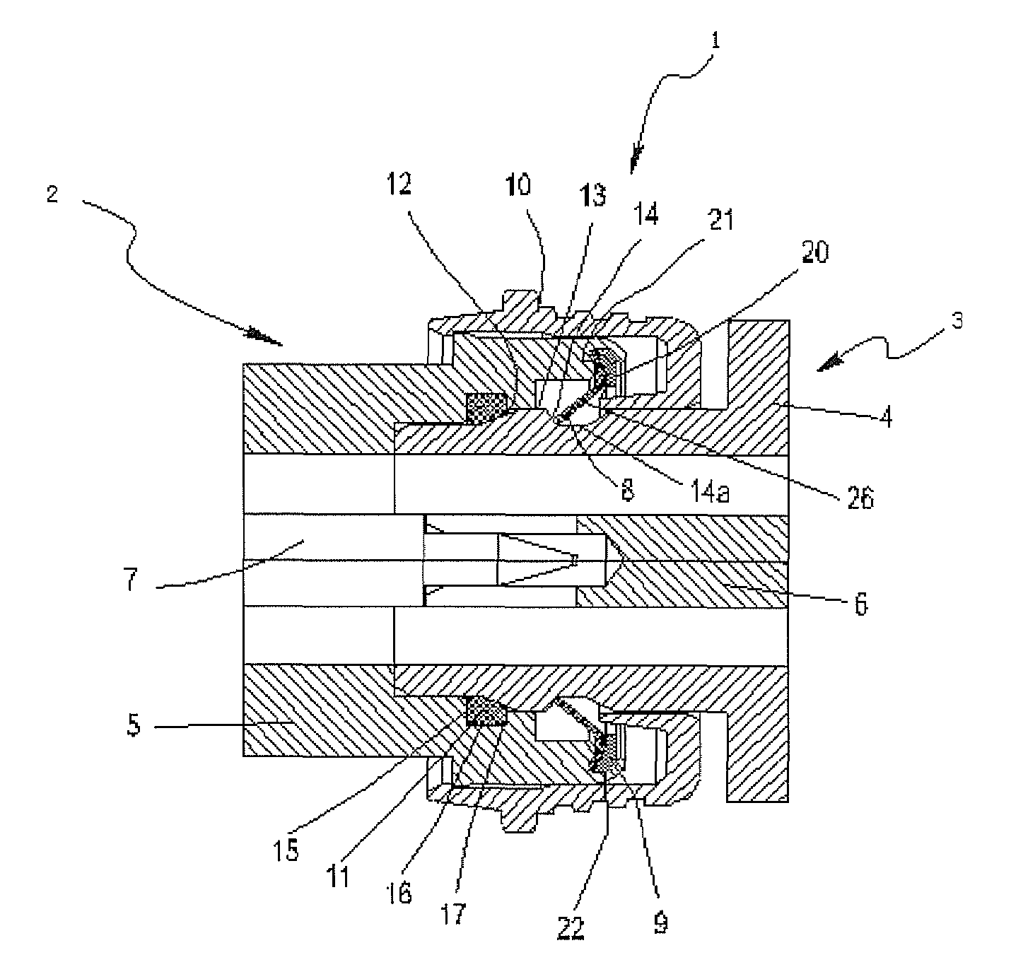
[0033]According to an embodiment of the present invention, as shown in FIG. 1, an electrical connector with self-locking by snap-fastening comprises a plug connector 2 and a socket connector 3.

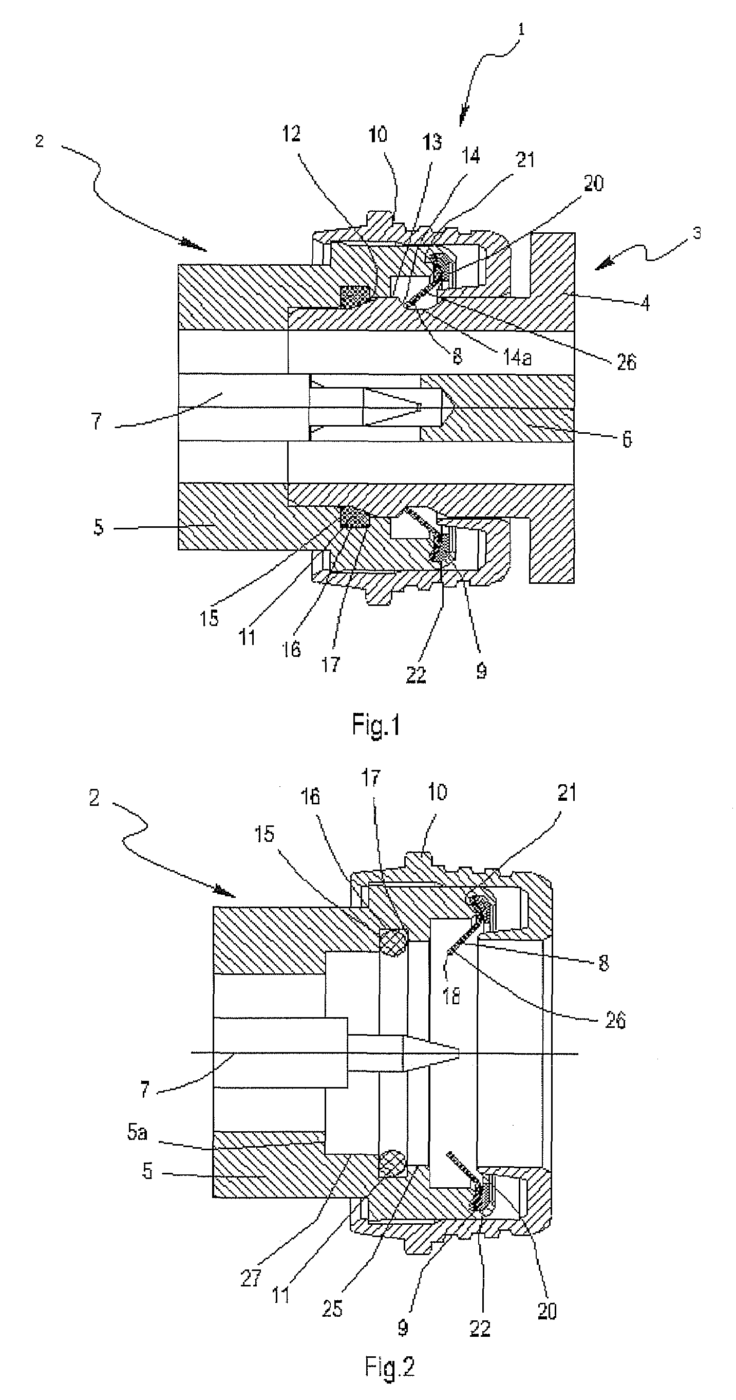
[0034]As shown in FIG. 2, the plug connector 2 comprises an outer conductor 5 and a core conductor 7. A ring-like locking sheet with inner and outer teeth 8 made of elastic material and a clamp ring 9 are arranged in portions 21, 22 of the outer conductor 5, and an unlocking sleeve 10 is mounted on the radial exterior of the outer conductor 5. On the inner surface of the outer conductor 5, there is a circumferential groove defined by inner walls 15, 16, 17 with an O-ring seal in it.

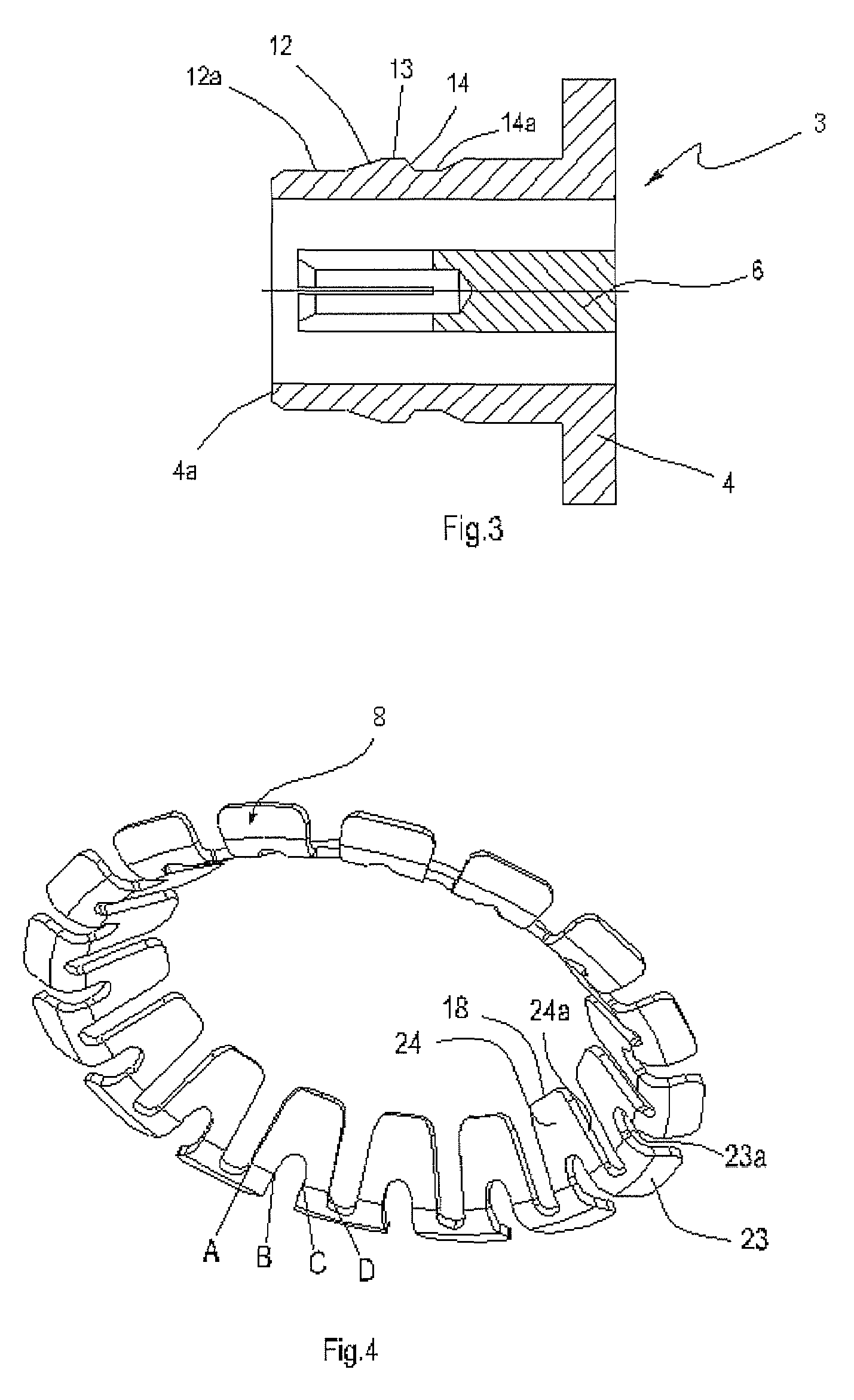
[0035]As shown in FIG. 3, the socket connector 3 comprises an outer conductor 4 and a core conductor 6 which is made of elastic material with an end hole facing the conductor 7. Several longitudinal slits are provided on the wall of the end hole to make the core conductor 6 elastic, and therefore easy connecting wit...


PUM


Abstract

An electrical connector, a ring-like locking sheet with inner and outer teeth of which is fixed at the end of its plug connector; and a circumferential bulge, with trapezoid cross section which has an upslope, a flat top and a down-slope, is provided on the surface of the outer conductor of the socket connector. Therefore, in the process of connection, the inner teeth reach the max flexural deformation when go up along the slope to the flat top. When reach the down-slope, the deformed inner teeth gradually restore the original state in tangential direction of the down-slope, and finally stop at the down-slope or at the juncture of the down-slope and the flat top. The electrical connector according to the present invention can have a rigid zero clearance between the interfaces in connection, and at the same time can keep a very strong axial force. The RF coaxial connector according to the present invention has continuous impedance between the contact surfaces, reliable and stable contact, greatly reduced RF emission, as well as the same operating frequency, excellent RF performance and good passive intermodulation as those with threaded connection.

Description

FIELD OF THE INVENTION[0001]The present invention is related to an electrical connector, in particular, an electrical connector with self-locking by snap-fastening. The RF coaxial connector according to the present invention has continuous impedance on the contact surfaces between its plug and socket, with little reflection caused by the transmission of electromagnetic waves on the contact surfaces and therefore with greatly reduced RF emission.PRIOR ART[0002]U.S. Pat. No. 6,709,289B2 discloses an electrical connector with self-locking by snap-fastening, making use of the elasticity of an elastic element 42 to eliminate the clearance between the contact surfaces 46, 47 caused by the machining error of the spare parts 35, 38, and at the same time to gain the axial forces between the plug 35 and the socket 38 by the elasticity of said elastic element 42. However, there exists such a problem that the impedance between the plug 35 and the socket 38 is discontinuous in the position of th...

Claims


Application Information

Patent Timeline
Patent Type & Authority Patents(United States)
IPC IPC(8): H01R13/627H01R13/646
CPCH01R13/5219H01R13/6277H01R24/40H01R2103/00
Inventor QU, JINLIANG
Owner ANOISON ELECTRONICS JIANGSU
Why Eureka
Try Eureka