Automated microwave turntable

a turntable and turntable technology, applied in the field of microwave turntables, can solve the problems of preventing the achievement of all performance requirements, illusory achievement of a suitable on/off switch for microwave turntables,

Inactive Publication Date: 2008-04-01
KUBLER KENNETH
View PDF3 Cites 5 Cited by
  • Summary
  • Abstract
  • Description
  • Claims
  • Application Information

AI Technical Summary

Benefits of technology

[0017]The assembly further includes a mechanism for independently rotating the drive gear after a cooking time of the microwave cooking device has lapsed such that the annular body effectively terminates at a position identical to the initial position and thereby advantageously insures that an item placed on the body conveniently remains identically oriented at a beginning and an ending of the cooking time.
[0018]The drive gear rotating mechanism includes a linear peg that protrudes upwardly from a top surface of the drive gear and is positioned along an outer edge thereof. The rotating mechanism further in

Problems solved by technology

Achievement of a suitable on/off switch for microwave turntables has proven illusive.
While the above switch mechanism works well, it has certain deficiencies which prevent it from achieving all of the above-discussed performance requirements.
First, operation of a sliding switch is cumbersome and can result in the turntable being pushed or pulled in jarring fashion.
Undesired spillage of food stuffs supported by the turntable can result.
Further, sliding actuation can cause the tooth of the sliding mechanism to stub against the gear teeth along the rim flange.
However, such a procedure in the small confines of a microwave oven is awkward and can, again, result

Method used


Image

  • Automated microwave turntable
  • Automated microwave turntable
  • Automated microwave turntable

Examples


Embodiment Construction

[0030]The present invention will now be described more fully hereinafter with reference to the accompanying drawings, in which a preferred embodiment of the invention is shown. This invention may, however, be embodied in many different forms and should not be construed as limited to the embodiment set forth herein. Rather, this embodiment is provided so that this application will be thorough and complete, and will fully convey the true scope of the invention to those skilled in the art. Like numbers refer to like elements throughout the figures.

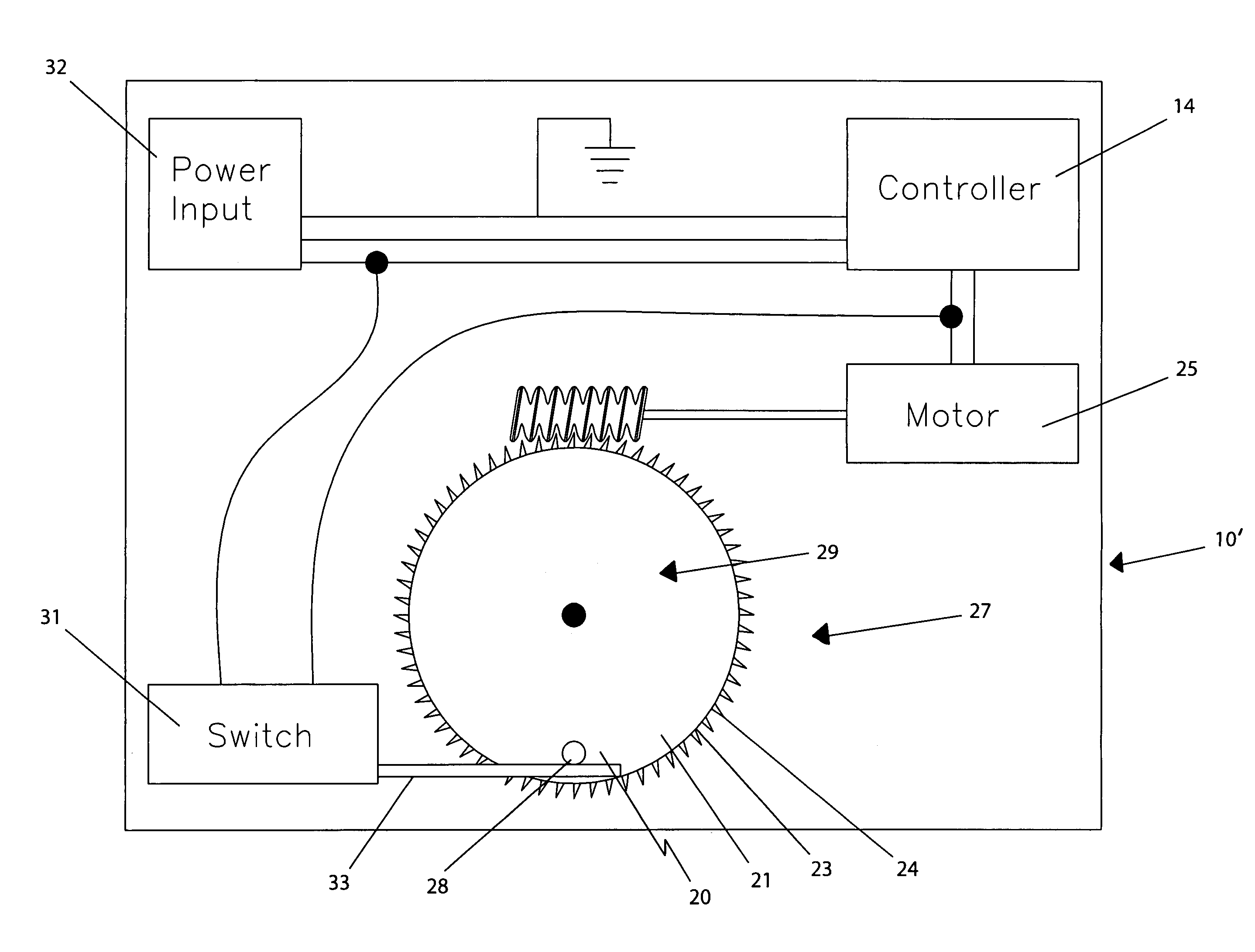
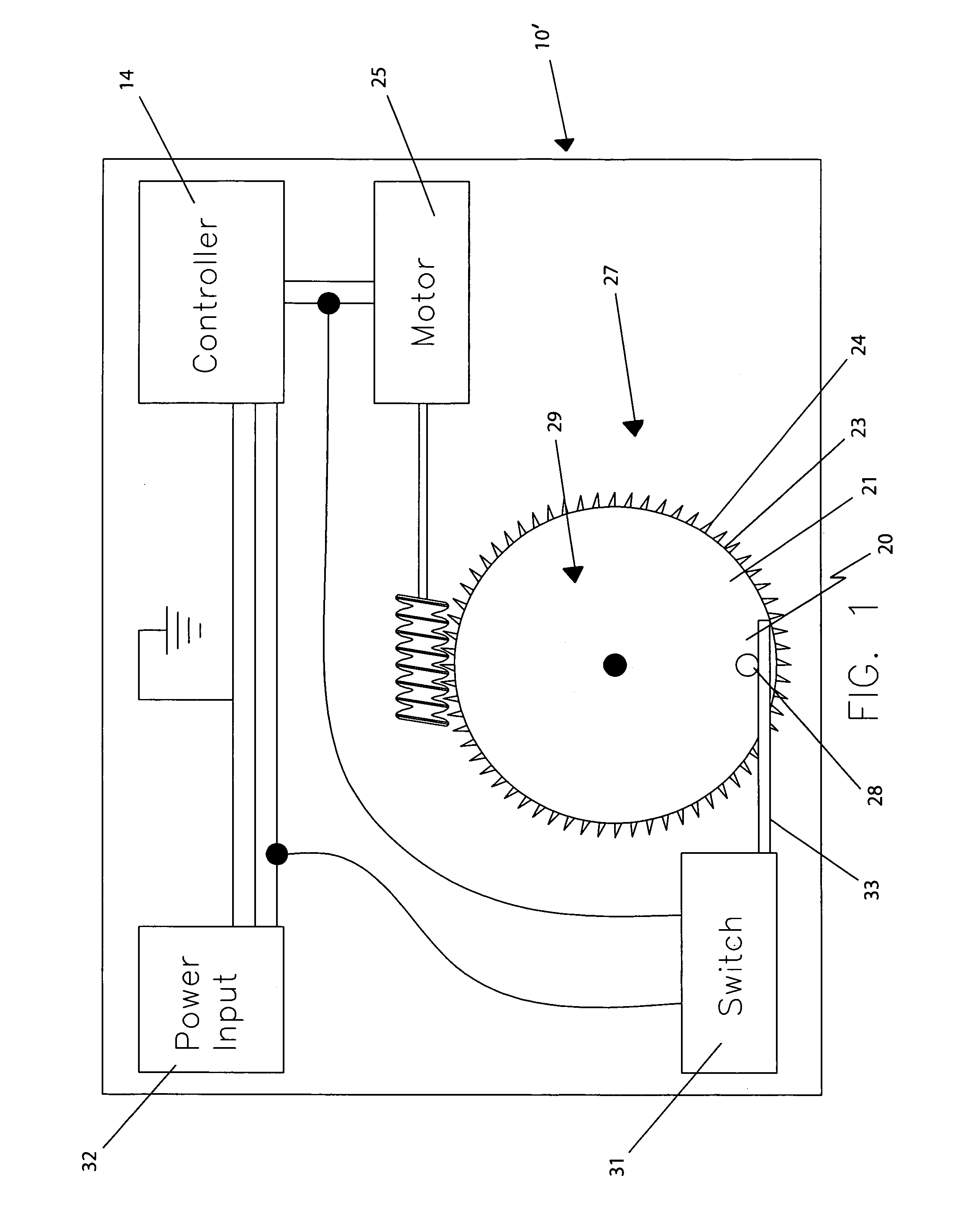
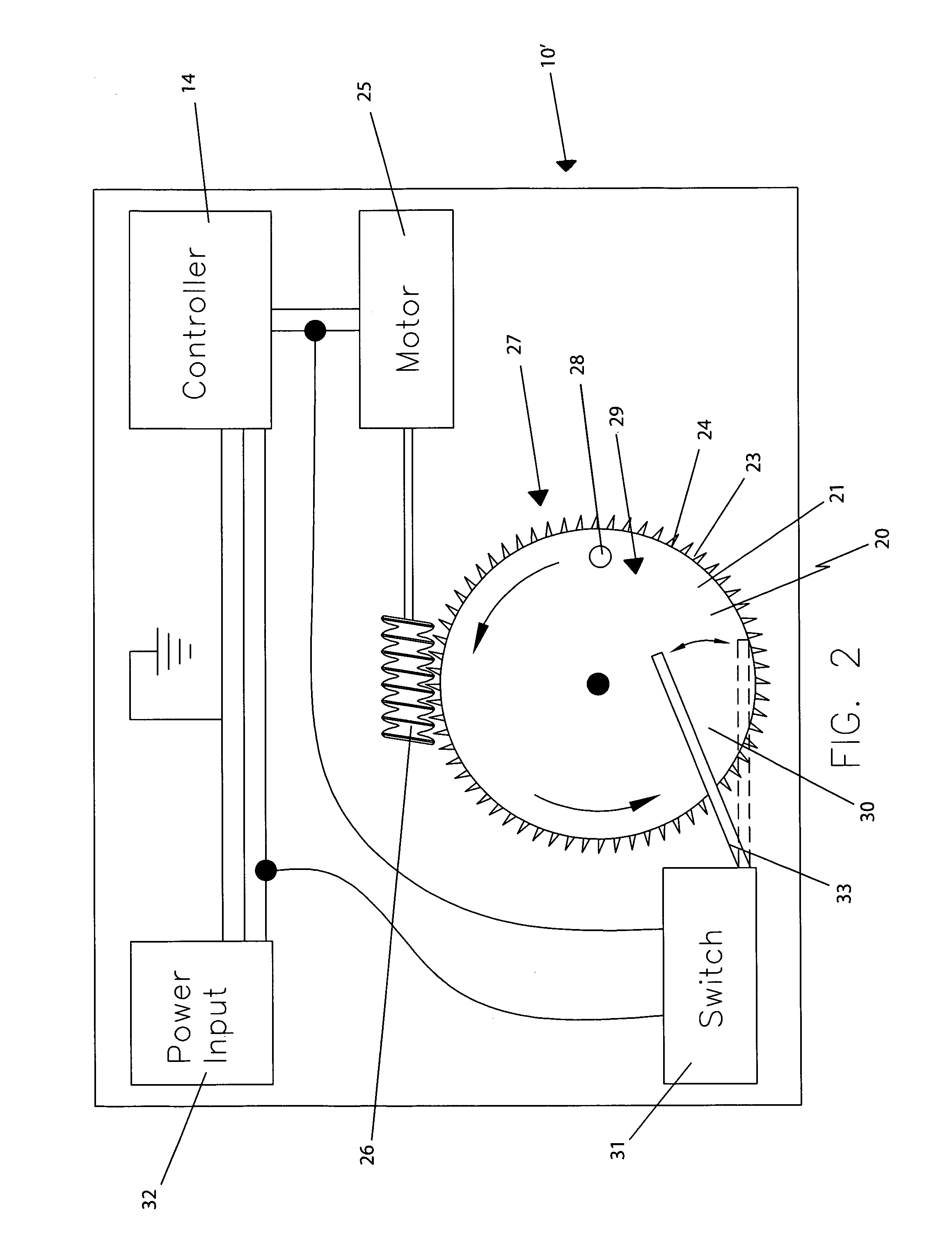
[0031]The assembly of this invention is referred to generally in FIGS. 1-6 by the reference numeral 10 and 10′ is intended to provide an automated microwave cooking device turntable. It should be understood that the assembly 10 and 10′ may be used as an automated turntable with many different types of devices and should not be limited in use to providing an automated turntable only for those types of devices described herein.

[0032]Referring i...


PUM


Abstract

An automated microwave cooking device turntable assembly includes an anchor member nested to a bottom surface of a microwave cooking device and extending upwardly within a cavity thereof. A drive gear is journaled about the anchor member and rotatable along a counter clockwise direction, and a body is seated on the drive gear and coupled thereto. A mechanism rotates the drive gear such that the annular body terminates at a position that insures that an item placed on the body remains identically oriented at a beginning and an ending of the cooking time. The rotating mechanism includes a peg that protrudes upwardly from the drive gear and is positioned along an outer edge thereof. A motor is coupled to the drive gear, and a switch is coupled to the motor and a power supply source respectively. An actuating arm is coupled to the switch.

Description

CROSS REFERENCE TO RELATED APPLICATIONS[0001]This application claims the benefit of U.S. Provisional Application No. 60 / 742,223, filed Dec. 5, 2005, the entire disclosures of which are incorporated herein by reference.STATEMENT REGARDING FEDERALLY SPONSORED RESEARCH OR DEVELOPMENT[0002]Not Applicable.REFERENCE TO A MICROFICHE APPENDIX[0003]Not Applicable.BACKGROUND OF THE INVENTION[0004]1. Technical Field[0005]This invention relates to microwave turntables and, more particularly, to an independently actuated turntable assembly for use with a microwave cooking device having an access door provided with a planar front edge registered along a front face of the microwave.[0006]2. Prior Art[0007]Portable turntables for microwave ovens are known and are commonly available in consumer markets. Such devices typically comprise a stationary base, a rotatable platform mounted to the base, and a drive motor. An on / off switching mechanism is generally provided to control the rotational movement ...

Claims


Application Information

Patent Timeline
IPC IPC(8): H05B6/78F24C7/02
CPCH05B6/6411H05B6/66
Inventor KUBLER, KENNETH
Owner KUBLER KENNETH
Why Eureka
Try Eureka