Flat-plate MIMO array antenna with isolation element

a technology of array antenna and isolation element, which is applied in the structure of radiating element, antenna coupling, resonance antenna, etc., can solve the problems of increasing the overall volume of the antenna chip, affecting the performance of the antenna, so as to prevent the distortion of the radiation pattern with the increase of the output gain

Active Publication Date: 2008-04-01
SAMSUNG ELECTRONICS CO LTD
View PDF12 Cites 50 Cited by
  • Summary
  • Abstract
  • Description
  • Claims
  • Application Information

AI Technical Summary

Benefits of technology

[0012]An aspect of the present invention is to provide a flat-plate MIMO array antenna having a plurality of antenna elements disposed on a substrate in a shape of a flat-plate, in which interference of the antenna elements is prevented by offsetting electromagnetic waves radiated from a plurality of the antenna elements and propagated to other antennas, and distortion of a radiation pattern is prevented with its output gain increased.
[0013]Another aspect of the present invention is to provide a flat-plate MIMO array antenna which can be easily manufactured in a compact size.
[0015]At least one of the isolation elements may cancel an influence in which an electromagnetic wave radiated from each antenna element affects other antenna elements.

Problems solved by technology

Since a plurality of antenna elements are used, a problem occurs wherein the mutual coupling resulting from interference between the antenna elements distorts the radiation pattern of the antenna.
However, since the related art method employs the 3-dimensional configuration, the overall volume of the antenna chip is increased, so that it is difficult to use the antenna in a micro electronic device.
Further, there are other drawbacks in that the manufacture itself is difficult, and the integration of the manufactured product is also difficult, causing manufacturing cost to increase significantly.

Method used


Image

  • Flat-plate MIMO array antenna with isolation element
  • Flat-plate MIMO array antenna with isolation element
  • Flat-plate MIMO array antenna with isolation element

Examples


Embodiment Construction

[0036]Certain exemplary embodiments of the present invention will be described in greater detail with reference to the accompanying drawings.

[0037]In the following description, the same drawing reference numerals are used for the same elements throughout the drawings. The matters defined in the description such as a detailed construction and elements are only provided to assist understanding of the invention. However, the present invention can be realized in manners different from those disclosed herein. Also, well-known functions or constructions are not described in detail since they would obscure the invention in unnecessary detail.

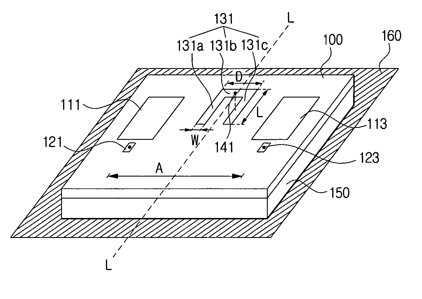
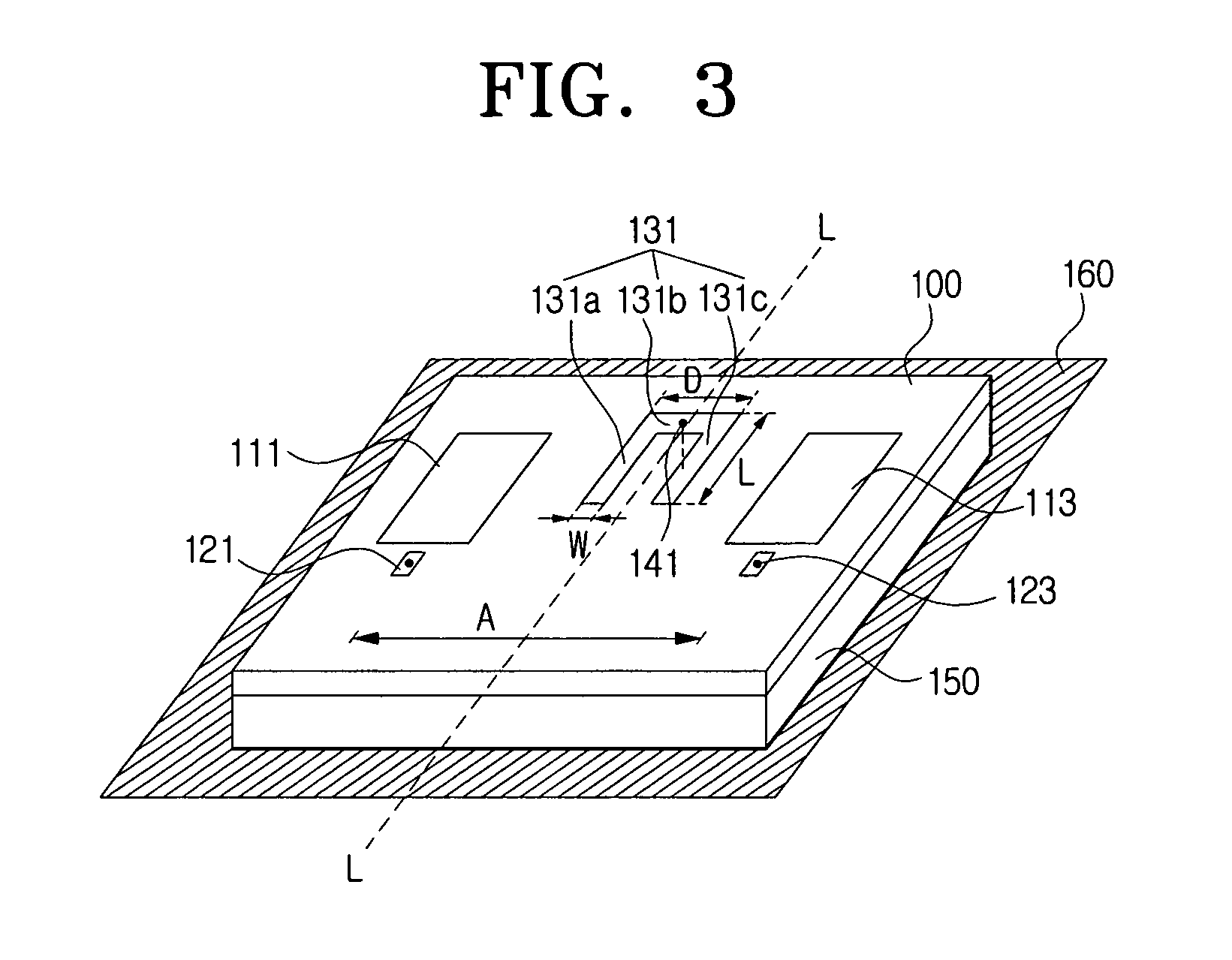
[0038]FIG. 3 is a view illustrating a MIMO array antenna according to an exemplary embodiment of the present invention, in which a 2-channel flat-plate array antenna has an isolation element according to the present invention.

[0039]The MIMO array antenna in FIG. 3 includes first and second antenna elements 111 and 113 disposed on a substrate 100 in sha...


PUM


Abstract

A flat-plate MIMO array antenna includes a substrate, a plurality of antenna elements disposed on the substrate, and at least one isolation element interposed between a plurality of antenna elements on the substrate and connected to a ground. Mutual interference between the antenna elements is prevented by the isolation element formed between the antenna elements, thereby preventing the distortion of the radiation pattern. Also, since the isolation element is grounded to the ground surface, the isolation element operates as a parasitic antenna, thereby increasing the output gain.

Description

[0001]This application claims priority from Korean Patent Application No. 10-2005-0089925, filed on Sep. 27, 2005, the entire content of which is incorporated herein by reference.BACKGROUND OF THE INVENTION[0002]1. Field of the Invention[0003]Apparatuses and methods consistent with the present invention relate to a flat-plate multiple input and multiple output (MIMO) array antenna, and more particularly, to a flat-plate MIMO array antenna that is formed on a substrate in a shape of a flat plate and has an isolation element for preventing interference between antenna elements.[0004]2. Description of the Related Art[0005]An antenna is a component for converting an electric signal into a specified electromagnetic wave to radiate the wave into a free space and vice versa. An effective area in which the antenna radiates or detects the electromagnetic wave is generally referred to as a radiation pattern. A plurality of antenna elements may be arranged in a specific structure to combine ra...

Claims


Application Information

Patent Timeline
Patent Type & Authority Patents(United States)
IPC IPC(8): H01Q1/38H01Q1/52H01Q21/00
CPCH01Q1/521H01Q1/523H01Q21/065H01Q1/38
Inventor MOON, YOUNG-MINKIM, YOUNG-EILPARK, SE-HYUNMIN, KYEONG-SIK
Owner SAMSUNG ELECTRONICS CO LTD
Why Eureka
Try Eureka