Display system having a three-dimensional convex display surface

a display system and convex display technology, applied in the field of projection display systems, can solve the problems of high manufacturing cost, easy detection of seams, and high manufacturing cost of systems, and achieve the effects of reducing production costs, reducing production costs, and increasing production costs

Active Publication Date: 2008-04-01
GLOBAL IMAGINATION
View PDF20 Cites 36 Cited by
  • Summary
  • Abstract
  • Description
  • Claims
  • Application Information

AI Technical Summary

Problems solved by technology

In one category, the display system includes multiple elements that individually conduct and emit light, for example as shown in U.S. Pat. No. 5,030,100, “Environmental Display System.” However, these systems typically are expensive and difficult to manufacture.
However, this results in seams that often can be easily detected by the viewer.
They can be substantially more expensive to manufacture, assemble, and align than a system that uses only a single projector.
This class of display systems is not well suited for transmissive displays (i.e., displays viewed from the exterior) or to display surfaces of smaller size, for example under a few feet in diameter, due to the size and complexity of arranging the image sources and projection optics.
Convex reflectors form the basis of another category, as exemplified in U.S. Pat. No. 6,327,020, “Full-Surround Spherical Screen Projection System And Recording Apparatus Therefor.” However, these systems also suffer from a number of limitations.
One significant drawback is that these systems typically have dead zones where no light is visible.
In addition, the convex mirror is substantially larger than the projector, resulting in a much larger dead zone than that generated by the projector alone.
However, these displays are typically limited to external viewing.
Furthermore, they are generally expensive because they require a substantial amount of custom electronics and complex mechanical mechanisms.
These can also lead to reliability issues.
This general class is also not very mature as a technology or an industry.
Thus, they typically have low resolution and a limited range of colors.

Method used


Image

  • Display system having a three-dimensional convex display surface
  • Display system having a three-dimensional convex display surface
  • Display system having a three-dimensional convex display surface

Examples


Embodiment Construction

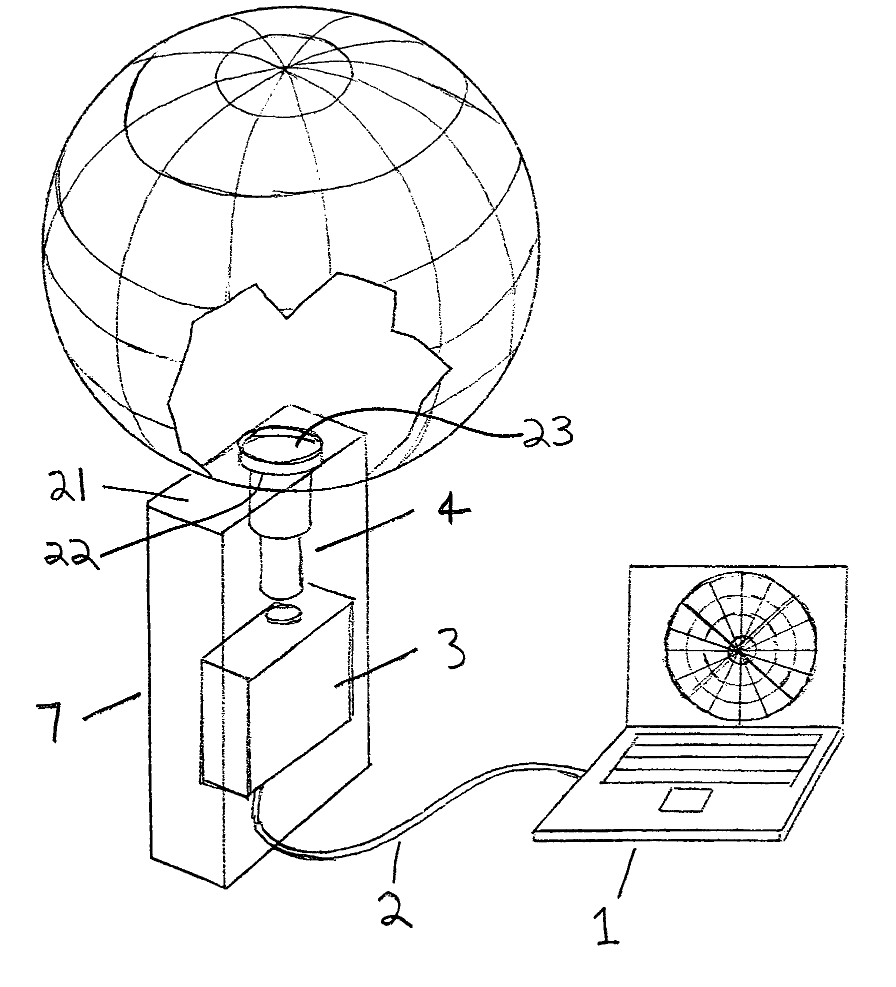
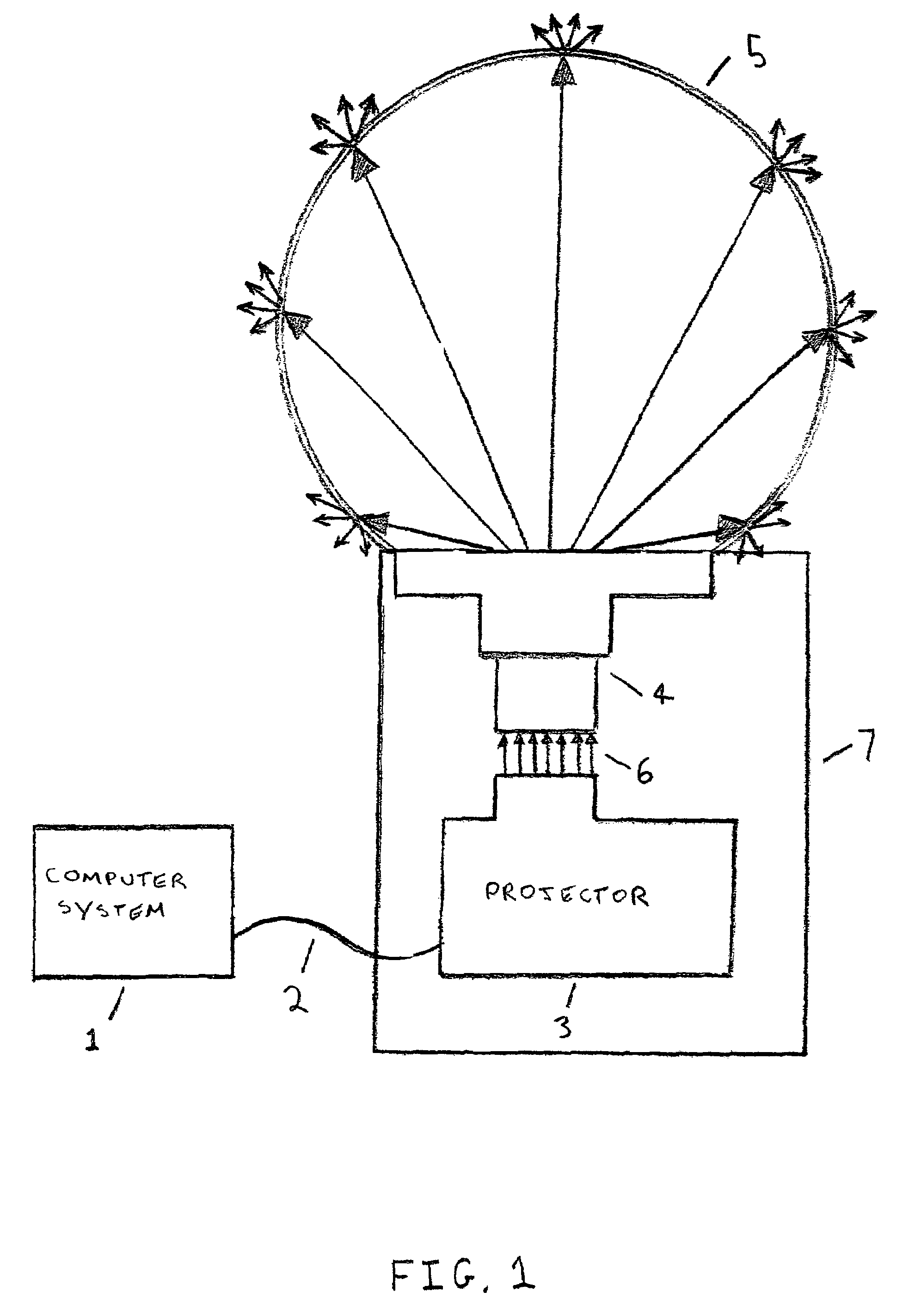
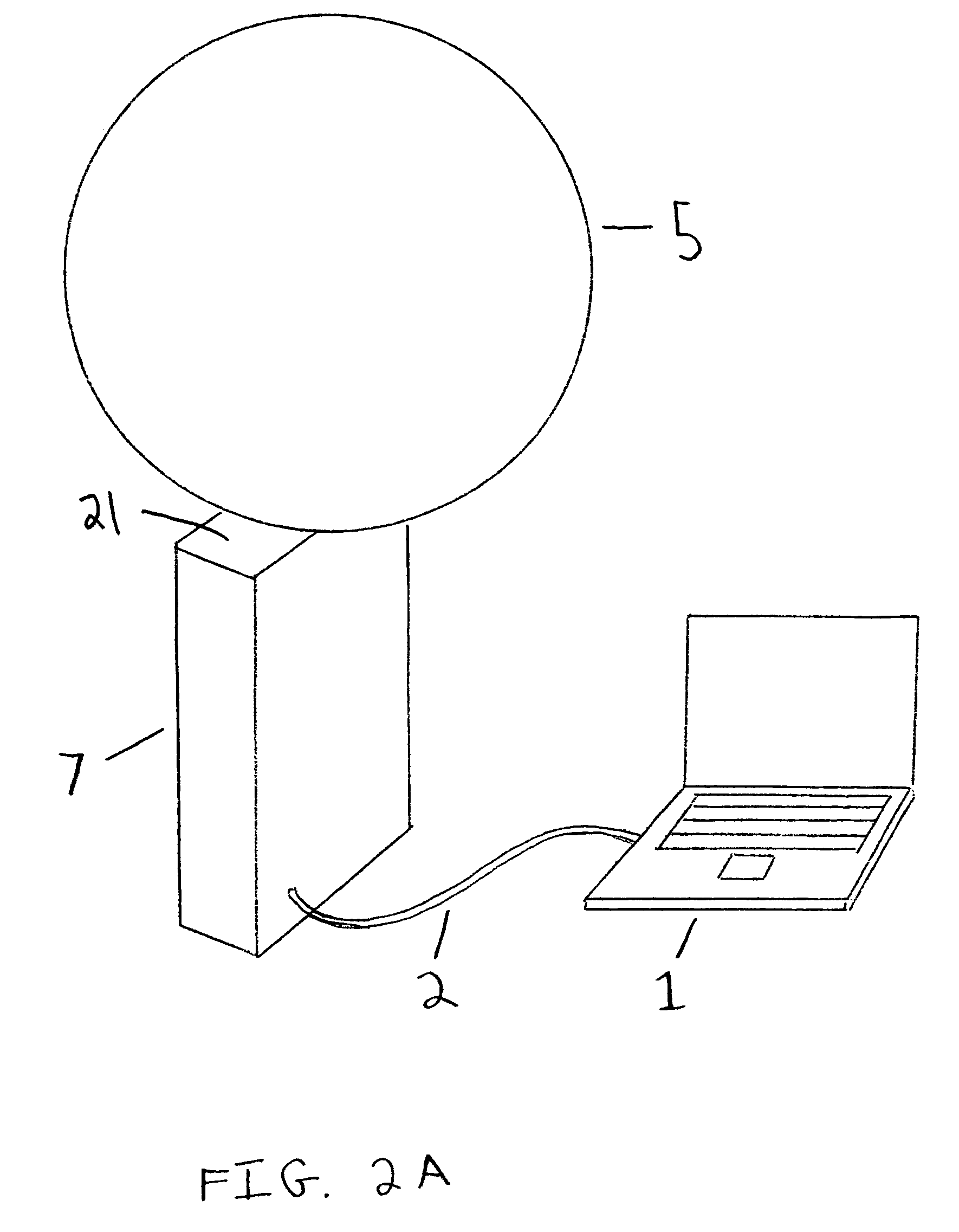
[0030]FIG. 1 is a cross sectional view of an example display system according to the invention. It includes a display surface 5 that has a three-dimensional convex shape, and a projection system 7. The projection system projects an object field onto a continuous image field that has the same shape as the display surface 5, thus forming a displayed image.

[0031]The example of FIG. 1 also includes a computer system 1 that is connected to the projection system 7 by a computer video cable 2. The projection system 7 includes a projector 3 (in this case, a digital video projector) and a lens system 4. A video output port of the computer system 1 is connected by cable 2 to the digital video projector 3. The digital video projector 3 takes as input a video signal from the computer system 1 and displays the video signal onto an electronically controlled display, for example a liquid crystal display. In the absence of the rest of the system, the optics in the projector 3 would project the flat...


PUM


Abstract

A display system has a display surface having a three-dimensional convex shape. A projection system projects an object field onto a continuous image field located on the interior of the display surface the display surface is extensive in its coverage, for example subtending an angle of at least 240 degrees to provide greater hemispherical coverage.

Description

CROSS-REFERENCE TO RELATED APPLICATION[0001]This application claims priority under 35 U.S.C. § 119(e) to U.S. Provisional Patent Application Ser. No. 60 / 435,973, “Display System Having a Three-dimensional Convex Display Surface,” by Steven W. Utt et al., filed Dec. 20, 2002, the subject matter of which is incorporated herein by reference in its entirety.BACKGROUND OF THE INVENTION[0002]1. Field of the Invention[0003]This invention relates generally to projection display systems and, more specifically, to projection display systems capable of projecting images onto a three-dimensional convex display surface that is greater than a hemisphere.[0004]2. Description of the Related Art[0005]In many fields of endeavor, it has been a long sought after goal to provide a display system that can generate an image that covers an entire sphere or, more generally, that covers the entire surface of some convex shape. Such a display system would have many different uses. For example, in the planetar...

Claims


Application Information

Patent Timeline
Patent Type & Authority Patents(United States)
IPC IPC(8): G09G3/00G03B21/14
CPCG09G3/003G03B21/14G03B37/00G09B27/08G09B29/007G03B21/10H04N5/74G09G5/00G03B21/00
Inventor UTT, STEVEN WRUBESIN, PHILIP CFOODY, MICHAEL A
Owner GLOBAL IMAGINATION
Why Eureka
Try Eureka