Check patentability & draft patents in minutes with Patsnap Eureka AI!

Gateway card, gateway apparatus, gateway control method, and computer product

Inactive Publication Date: 2008-04-01
FUJITSU LTD
View PDF9 Cites 19 Cited by
  • Summary
  • Abstract
  • Description
  • Claims
  • Application Information

AI Technical Summary

Benefits of technology

[0021]A computer program according to still another aspect of the present invention controls communications between different networks. The computer program allows a computer to execute the steps of retaining first apparatus authentication data for authenticating the server information processor, and receiving a setting request for system data of the gateway apparatus. The computer program also allows the computer to execute the step of obtaining second apparatus authentication data from either of a client information processor and the server information processor which has issued the setting request. The computer program further allows the computer to execute the steps of comparing the first apparatus authentication data with the second apparatus authentication data and permitting setting of the system data only if there is a match between both of the data as a result of the comparison.

Problems solved by technology

However, when a user newly purchases equipment having the Internet connection function, it is necessary to perform connection setting to an access point for connecting each equipment to the Internet so as to allow the respective equipment to access the Internet, but this setting requires time and energy.
This is also troublesome, causing a problem in that wiring becomes more complicated as the number of equipment is increased.
In most homes, however, it is almost impossible to expect an administrator having expertise in network equipment to control the gateway apparatus (home gateway).
Therefore, conventionally, ordinary users having no expertise perform the setting including initialization, modification, restoration, and storage of the system data.
However, the conventional gateway apparatus (home gateway) is targeted for an ordinary user, and therefore advanced operation for ensuring the security cannot be expected.
Thus, it is difficult to satisfy such needs.
In view of these problems, the conventional gateway apparatus (home gateway) currently has many problems to be solved by the time when the gateway apparatus becomes widespread in respective homes.

Method used


Image

  • Gateway card, gateway apparatus, gateway control method, and computer product
  • Gateway card, gateway apparatus, gateway control method, and computer product
  • Gateway card, gateway apparatus, gateway control method, and computer product

Examples


first embodiment

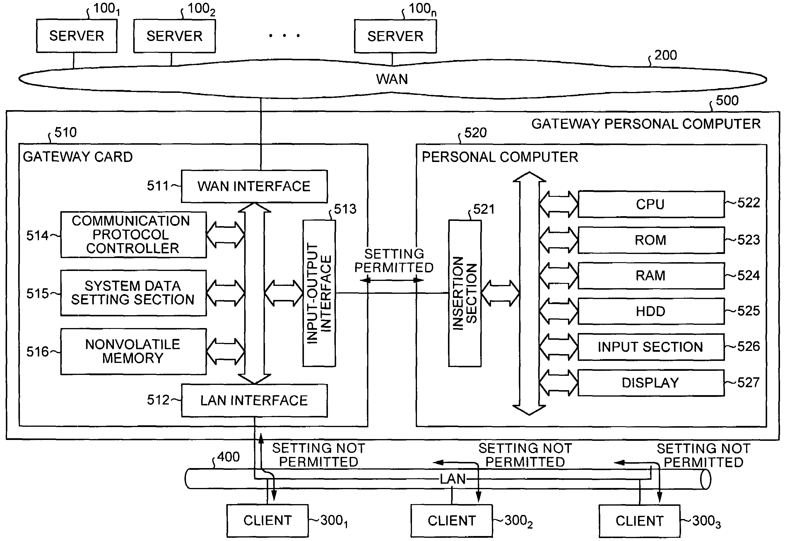
[0033]FIG. 1 is a block diagram of the configuration according to the present invention. This figure illustrates a communication system in which a Wide Area Network (WAN) 200 and a Local Area Network (LAN) 400 having different communication protocols and standards are connected to each other via a gateway personal computer 500.

[0034]The WAN 200 is a wide area network including the Internet, public telephone networks, radio communication networks, Cable Television (CATV) networks, and the like, and connects computers in remote areas with each other according to a predetermined communication protocol. Servers 1001 to 100n are mail servers, World Wide Web (WWW) server, or the like, and are connected to the WAN 200.

[0035]These servers 1001 to 100n provide mail service, WWW site service, and the like to clients 3001 to 3003 via a gateway personal computer 500 described later and the LAN 400.

[0036]The clients 3001 to 3003 are, for example, client information processors installed in houses...

second embodiment

[0080]FIG. 4 is a block diagram of the configuration according to the present invention. In this figure, the parts corresponding to the respective sections in FIG. 1 are denoted by the same reference signs, and the explanation thereof is omitted.

[0081]In FIG. 4, a gateway apparatus 600 is provided instead of the gateway personal computer 500 shown in FIG. 1.

[0082]The gateway apparatus 600 is a gateway dedicated apparatus installed, for example, in home, that provides a function as a (home) gateway (for example, a router function, and a bridge function), and is inserted between the WAN 200 and the LAN 400 having a different communication protocol from each other.

[0083]The gateway apparatus 600 is an apparatus that enables interconnection by adjusting the difference in the communication protocol between the WAN 200 and the LAN 400.

[0084]In using the gateway apparatus 600, the system data explained in the first embodiment must be set. Generally, at the time of shipping the gateway appa...

third embodiment

[0113]FIG. 7 is a block diagram of the configuration according to the present invention. In this figure, the parts corresponding to the respective sections in FIG. 4 are denoted by the same reference signs, and the explanation thereof is omitted.

[0114]In FIG. 7, a gateway apparatus 700 is provided instead of the gateway apparatus 600 shown in FIG. 4. In the gateway apparatus 700, a setting switch 701 is newly provided.

[0115]The gateway apparatus 700 is a gateway dedicated apparatus installed, for example, in home, that provides a function as a (home) gateway (for example, a router function, a bridge function, and the like), and is inserted between the WAN 200 and the LAN 400 having different communication protocols from each other.

[0116]The gateway apparatus 700 is an apparatus that enables interconnection, by adjusting the difference in the communication protocol between the WAN 200 and the LAN 400.

[0117]In using the gateway apparatus 700, the system data explained in the first emb...


PUM


Abstract

A gateway card includes an input-output interface detachably inserted into an insertion section of a personal computer provided with control authority, and a nonvolatile memory that stores control terminal authentication data such as data for a product name for authenticating the personal computer. The card also includes a system data setting section that receives a setting request for system data of the gateway card issued from a terminal and obtains terminal authentication data from the terminal. The system data setting section permits setting of the system data only if there is a match between the control terminal authentication data and the terminal authentication data as a result of comparison.

Description

BACKGROUND OF THE INVENTION[0001]1) Field of the Invention[0002]The present invention relates to a technology for preventing setting of system data by a malicious third party and erroneous setting of system data.[0003]2) Description of the Related Art[0004]As well known, with popularization of the Internet, an Internet connection function is provided not only in a personal computer but also in various equipment such as a television and a telephone, thereby the Internet can be used in individual homes.[0005]However, when a user newly purchases equipment having the Internet connection function, it is necessary to perform connection setting to an access point for connecting each equipment to the Internet so as to allow the respective equipment to access the Internet, but this setting requires time and energy.[0006]Wiring for communication lines is necessary in individual houses for the equipment. This is also troublesome, causing a problem in that wiring becomes more complicated as the...

Claims


Application Information

Patent Timeline
IPC IPC(8): H04L12/28G06F21/34G06F13/00H04L12/66H04L29/06
CPCH04L63/02H04L63/08H04L12/2803H04L12/2807H04L2012/2841H04L2012/2845
Inventor KIMURA, MASATOSHINONAKA, KATSUYUKISUZUKI, SHUICHISAKUMA, SHIGEO
Owner FUJITSU LTD
Features
  • R&D
  • Intellectual Property
  • Life Sciences
  • Materials
  • Tech Scout
  • Unparalleled Data Quality
  • Higher Quality Content
  • 60% Fewer Hallucinations
Learn More