

Electronic toll collection system for toll road
a technology of electronic toll collection and toll road, applied in the direction of electric signalling details, instruments, roads, etc., can solve the problem that the system cannot automatically implement an accounting process with respect, and achieve the effect of stable wireless communication
- Summary
- Abstract
- Description
- Claims
- Application Information
AI Technical Summary
Benefits of technology
Problems solved by technology
Method used
Image

Examples
first embodiment
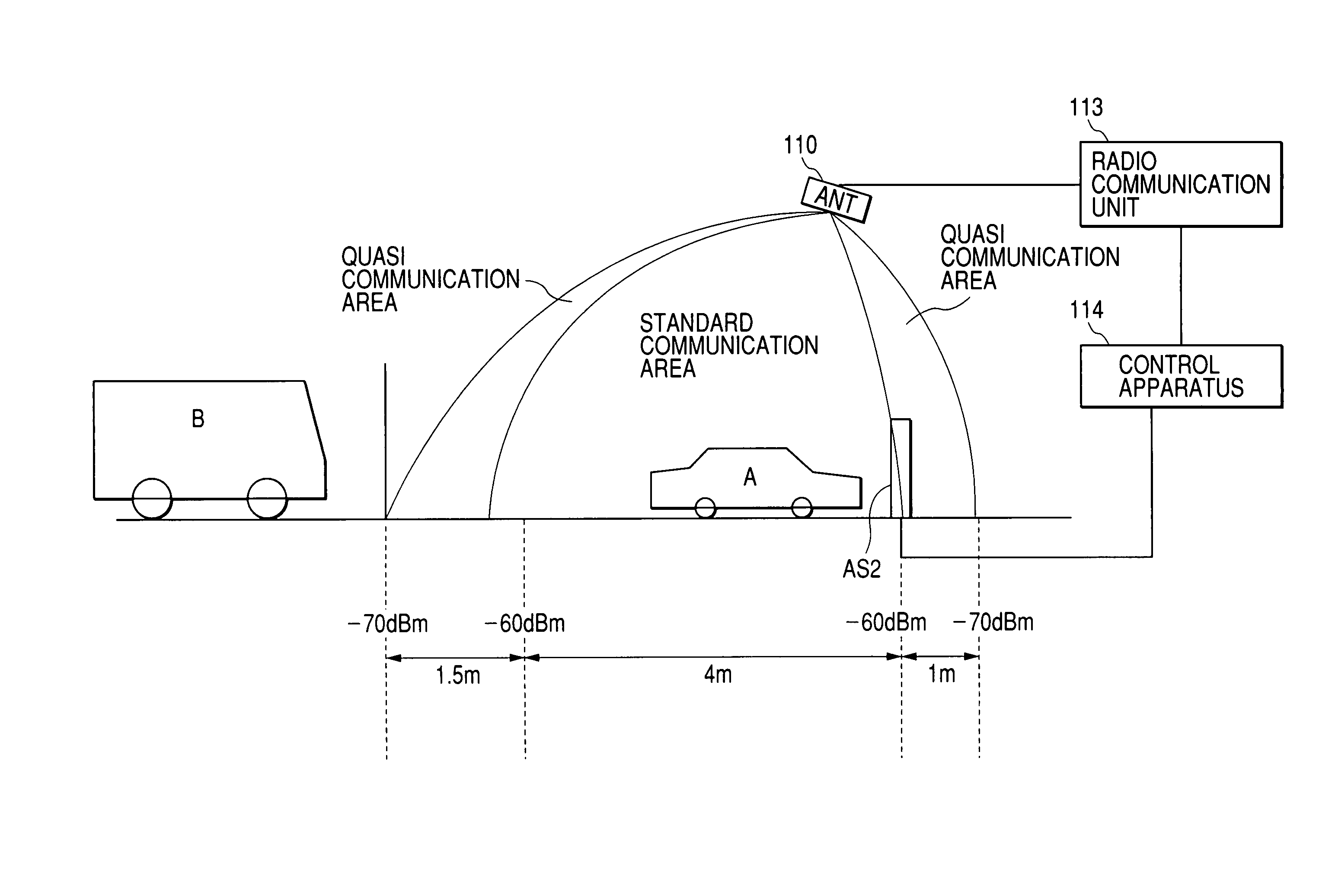
[0079]FIGS. 6, 7, and 8 show a tollgate in an ETC system (an electronic toll collection system) according to a first embodiment of this invention. With reference to FIGS. 6, 7, and 8, the tollgate includes a road-side antenna 110, a road-side indicator 111, a drive machine 112, a road-side radio communication unit 113, a control apparatus 114, and vehicle sensors AS2 and AS4. Here, “road-side” means “tollgate-side” opposite to “vehicle-side”.
[0080]The road-side antenna 110 is located above a lane. The road-side antenna 110 is connected to the road-side radio communication unit 113. There are islands 115 extending along the opposite sides of the lane. The load-side indicator 111 is located on one of the islands 115. The drive machine 112 is connected to a gate member associated with the lane. The drive machine 112 moves the gate member between an open position and a closed position. The control apparatus 114 is connected to the road-side indicator 111, the drive machine 112, the road...
second embodiment
[0102]FIGS. 10 and 11 show a tollgate in an ETC system according to a second embodiment of this invention. The tollgate in FIGS. 10 and 11 is similar to the tollgate in FIGS. 6, 7, and 8 except for additional designs mentioned later.
[0103]The tollgate in FIGS. 10 and 11 includes a vehicle sensor AS1 which is positionally equal to the rear edge of the standard radio-communication service area 118. The tollgate in FIGS. 10 and 11 includes a control apparatus 114A and a computer 150A instead of the control apparatus 114 and the computer 150 (see FIG. 8) respectively. The vehicle sensor AS1 is connected to the computer 150A within the control apparatus 114A.
[0104]FIG. 12 shows a segment of a program for the computer 150A (the control apparatus 114A). The program segment in FIG. 12 is similar to the program segment in FIG. 9 except that a step ST3A replaces the step ST3 (see FIG. 9).
[0105]The step ST3A decides whether or not “n” responses to the polling radio signal are received at a tim...
third embodiment
[0106]FIGS. 13, 14, and 15 show a tollgate in an ETC system according to a third embodiment of this invention. The tollgate in FIGS. 13, 14, and 15 is similar to the tollgate in FIGS. 6, 7, and 8 except for additional designs mentioned later.
[0107]The tollgate in FIGS. 13, 14, and 15 includes vehicle sensors AS1 and AS1A. The vehicle sensor AS1 is positionally equal to the rear edge of the standard radio-communication service area 118. The vehicle sensor AS1A extends ahead of the vehicle sensor AS1 by an interval of about 80 cm along the longitudinal direction of the lane. Thus, the position of the vehicle sensor AS1A corresponds to a position within the standard radio-communication service area 118. The tollgate in FIGS. 13, 14, and 15 includes a control apparatus 114B and a computer 150B instead of the control apparatus 114 and the computer 150 (see FIG. 8) respectively. The vehicle sensors AS1 and AS1A are connected to the computer 150B within the control apparatus 114B.
[0108]FIG...
PUM
| Property | Measurement | Unit |
|---|---|---|
| length | aaaaa | aaaaa |
| time | aaaaa | aaaaa |
| electric field strength | aaaaa | aaaaa |
Abstract
Description
Claims
Application Information