Gun barrel assembly

a barrel and barrel technology, applied in the field of firearms, can solve the problems of extreme rapid pressure increase, pressure increase and concomitant temperature increase in the system, and the level of energy required

Inactive Publication Date: 2008-04-08
BRIXIUS JOHN
View PDF50 Cites 33 Cited by
  • Summary
  • Abstract
  • Description
  • Claims
  • Application Information

AI Technical Summary

Problems solved by technology

In these more modern firearms, when the firing pin of the firearm strikes the cartridge's primer, the primer ignites the powder within the shell, causing an extremely rapid pressure increase, which causes the projectile to dislodge from the shell's open end, driving the projectile down the barrel of the firearm and out the end of the muzzle toward its target.
This constant volume expansion causes both a pressure increase and a concomitant temperature increase within the system.
This level of energy requires powders and loads that generate great temperatures and pressures within the barrel.
One problem resulting from this combination of high pressure and temperature is an increase in the wear of the barrel, and as a result, reduced barrel life.
This problem is exacerbated with higher pressure cartridges.
Also a problem is the high recoil of the high-pressure, heavy bullet systems common today.
These great recoils are not only sometimes uncomfortable or even damaging to the shooter, but greatly affect accuracy, target reacquisition, and sight realignment between shots.
Still another problem with these modern loads, particularly in tactical situations, is with respect to muzzle flash and report.
The problems with sound are, of course, obvious.
One that merits detailing is that the greater the muzzle report, the more likely the shooter, or shooters near to the shooter, will flinch in anticipation of the loud, harmful sound, causing a decrease in the marksmanship of the shooter.
In such cases, noise and debris is directed toward the shooter's face.
Problems with this scenario are also obvious, not the least of which is increased potential for damage to the shooter's, or nearby person's, eardrums, and pronounced shooter's flinch resulting in a further degradation of marksmanship.

Method used


Image

  • Gun barrel assembly
  • Gun barrel assembly
  • Gun barrel assembly

Examples


Embodiment Construction

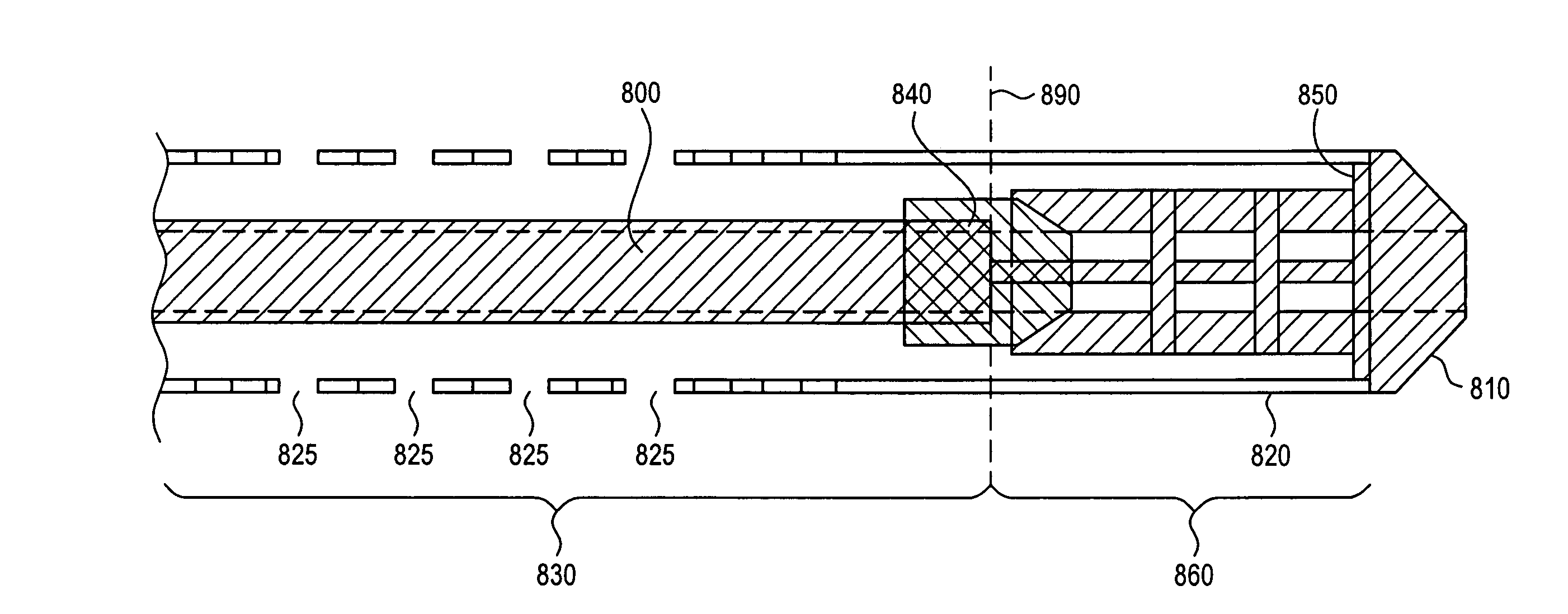
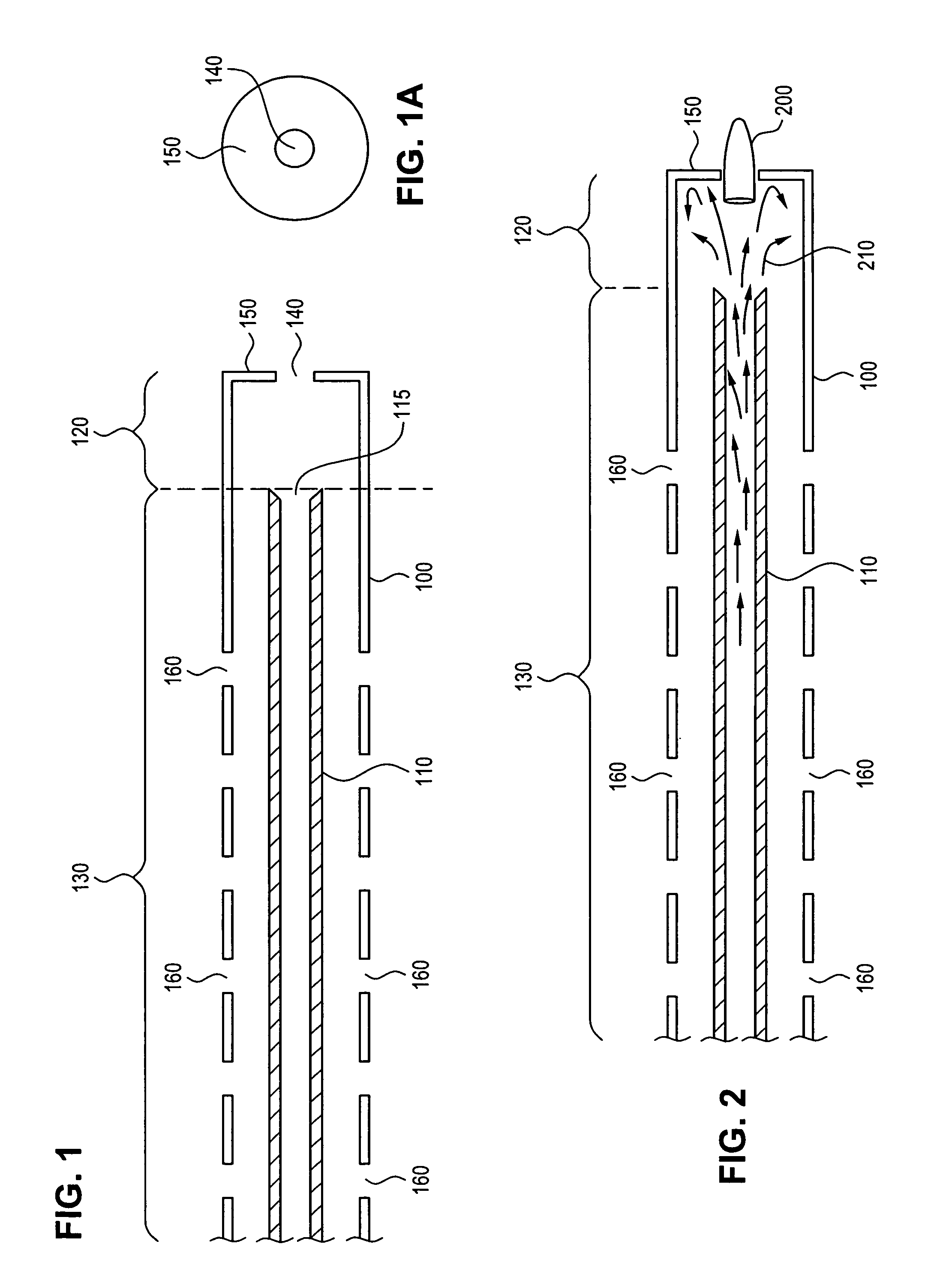
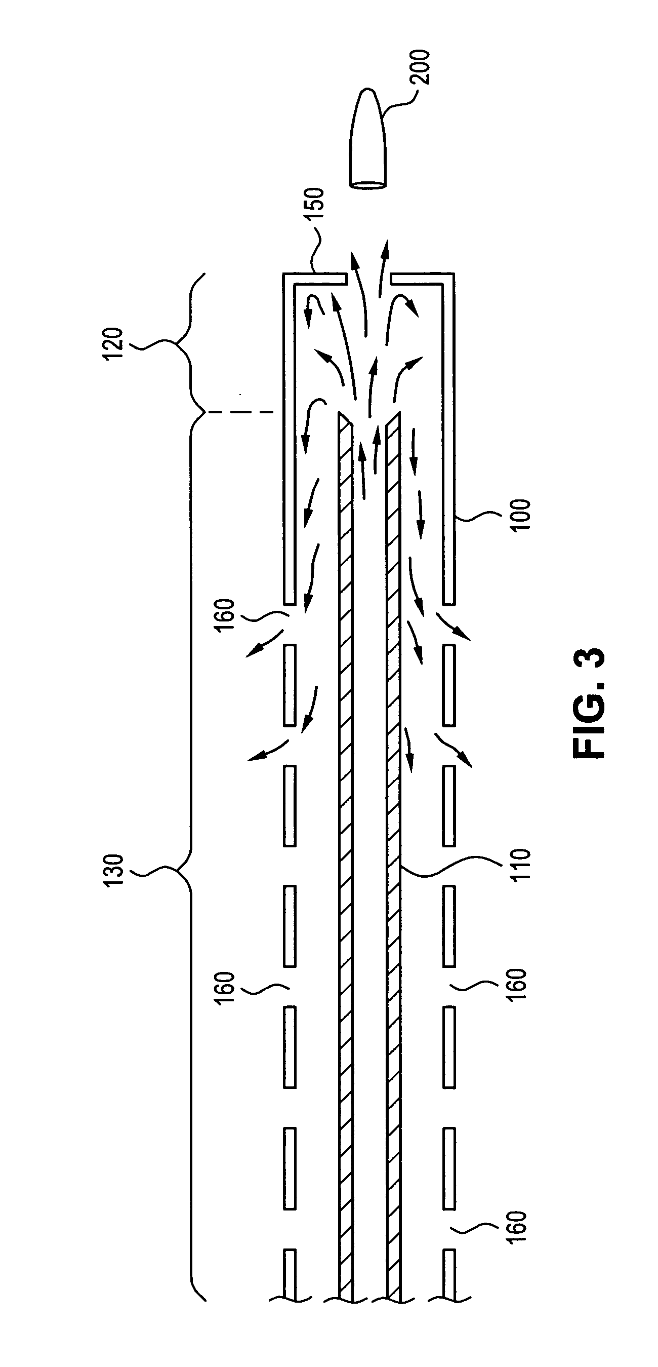
[0031]The present invention includes several features to improve firearm performance. It includes a barrel assembly and shroud which reduces felt recoil, reduces sound and muzzle flash, and has other features which combine to yield a firearm with substantially improved performance as compared to firearm systems of the prior art. In addition, preferred embodiments improve cooling, increase stiffness, and decrease the overall weight of the barrel unit.

[0032]Unless otherwise noted herein, the terms “distal” and “forward” and “front” all refer to a relative position away from a shooter in the direction of a projectile being fired, and the terms “proximal” and “rearward” and “rear” all refer to a relative position closer to the shooter with respect to the direction of a projectile being fired.

[0033]This invention is directed to a gun barrel assembly for firearms capable of shooting both “bullets” within their traditional meaning, as well as other projectiles which may not conventionally ...


PUM


Abstract

A firearm barrel assembly having a gun barrel with a muzzle opening on a distal end, a shroud coaxially surrounding at least a portion of the barrel, the shroud having a distal portion extending beyond the muzzle opening defining a shroud front region having a distal end portion, a proximal portion extending proximally from the muzzle opening defining an annular region between the barrel and shroud, the shroud front region and annular region in fluid communication with substantially no obstruction between the shroud front region and the annular region, and a front wall disposed at the distal end portion of the shroud. The wall has an opening to allow passage of a projectile fired from the firearm.

Description

[0001]This application claims the benefit of earlier filed U.S. Provisional Application Ser. No. 60 / 538,070 filed Jan. 20, 2004.FIELD OF INVENTION[0002]The present invention relates to firearms, and more specifically to firearm barrels and barrel assemblies, and how their design affects the performance of the firearm.BACKGROUND OF INVENTION[0003]Since the 13th century, firearms have operated on the principle that an explosive mass of powder, generally referred to as gun powder, could be ignited and caused to react and “explode” causing a sudden increase in pressure within a confined and defined space. This constant volume pressure increase was caused to happen behind a projectile, which was then forced in the one direction it could move, along with the exploding gas, which was down a barrel and out the end of a firearm muzzle. Early firearms were loaded down the muzzle, by first inserting a charge of gunpowder, and then on top of that powder adding a projectile, which was typically ...

Claims


Application Information

Patent Timeline
Patent Type & Authority Patents(United States)
IPC IPC(8): F41A21/36F41A13/00F41A13/06
CPCF41A13/06
Inventor BRIXIUS, JOHN
Owner BRIXIUS JOHN
Why Eureka
Try Eureka