High temperature completion plug

a technology of completion plugs and plugs, which is applied in the direction of valve housings, branching pipes, transportation and packaging, etc., can solve the problems of not being able to close an opening when a valve is not required and is not desirabl

Active Publication Date: 2008-04-08
TDW DELAWARE INC
View PDF34 Cites 15 Cited by
  • Summary
  • Abstract
  • Description
  • Claims
  • Application Information

AI Technical Summary

Benefits of technology

[0014]The completion plug is installed by moving the assembly of the completion plug, completion tool and insertion member into the flange fitting passageway. The insertion tool circumferential lip portion engages the upper end of the flange fitting, limiting further downward movement of the insertion tool relative to the flange fitting. However, additional downward force on the insertion member pushes the plug body downwardly past the completion tool lip portion. This allows the lock ring to expand outwardly and into the internal circumferential groove formed in the flange fitting. With the lock ring partially within the inner circumferential groove of the flange fitting and partially within the outer circumferential slot of the plug body, the plug body is locked in position within the flange fitting. The plug body circumferential sealing surface is then in metal-to-metal contact with the intermediate cylindrical surface of the flange fitting passageway providing a leak proof, heat resistant metal-to-metal seal thereby closing fluid flow through the flange fitting passageway.

Problems solved by technology

That is, to close an opening when a valve is not required and is not desirable.

Method used


Image

  • High temperature completion plug
  • High temperature completion plug
  • High temperature completion plug

Examples


Embodiment Construction

[0024]It is to be understood that the invention that is now to be described is not limited in its application to the details of the construction and arrangement of the parts illustrated in the accompanying drawings. The invention is capable of other embodiments and of being practiced or carried out in a variety of ways. The phraseology and terminology employed herein are for purposes of description and not limitation.

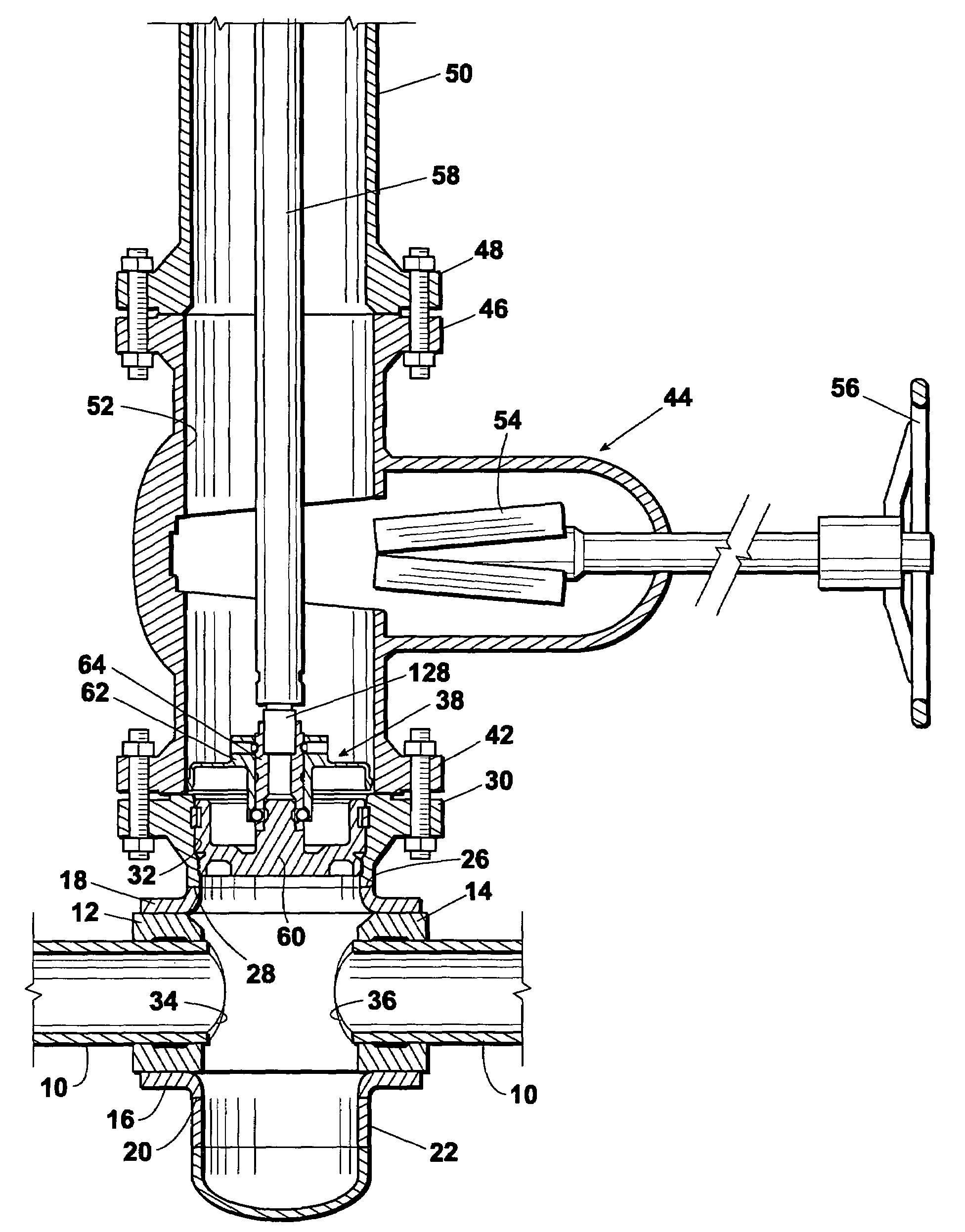
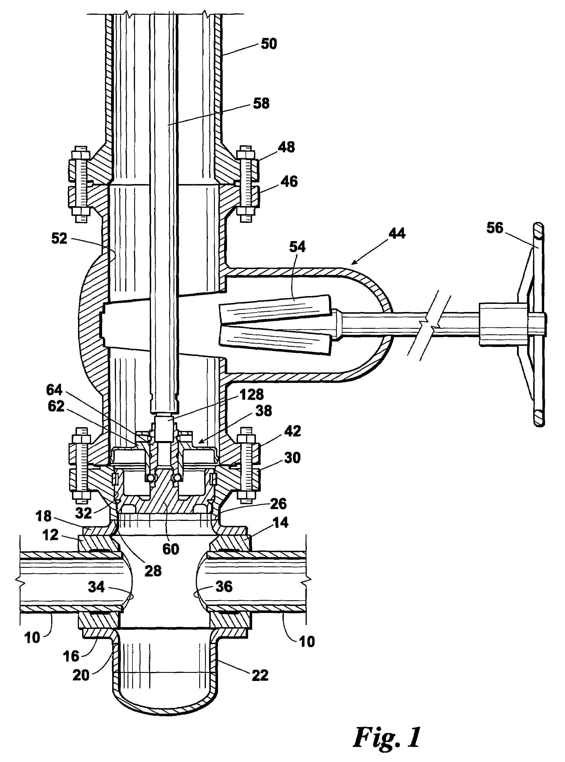
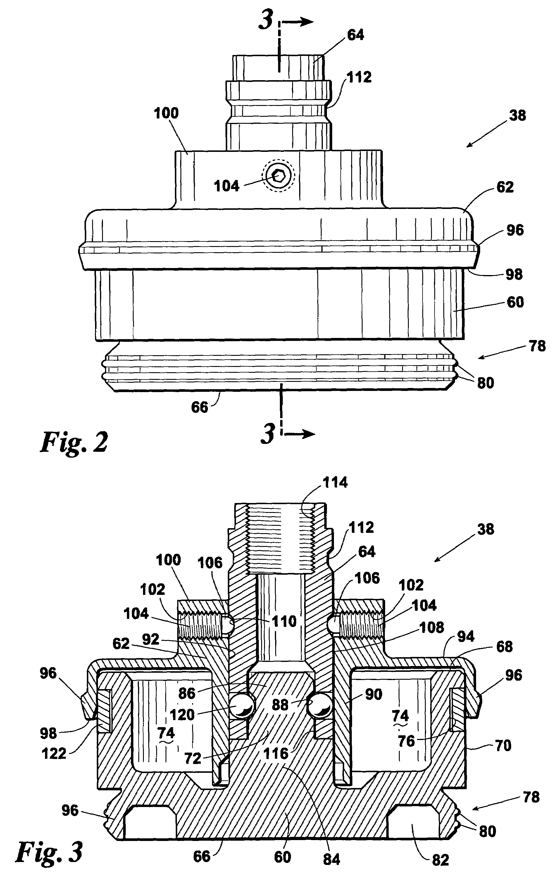
[0025]Elements illustrated in the drawings are identified by the following numbers:[0026]10 Pipe[0027]12 Collar[0028]14 Collar[0029]16[0030]18 Upper containment portion[0031]20 Bottom opening[0032]22 Tubular extension[0033]24 Closure head[0034]26 Cylindrical opening[0035]28 Bottom cylindrical opening[0036]30 Flange fitting[0037]32 Passageway through flange 30[0038]34 Exposed end of pipe 10[0039]36 Exposed end of pipe 10[0040]38 Completion plug assembly[0041]40 Top surface of flange 30[0042]42 Valve bottom flange[0043]44 Valve[0044]46 Top valve flange[0045]48 Bottom flan...


PUM


Abstract

For use in closing a cylindrical passageway through a working member in which the passageway is defined in part by a reduced diameter internal circumferential sealing surface and an internal locking groove, a completion plug having a plug body with a cylindrical external surface receivable within the cylindrical passageway of the working member and having an external circumferential sealing surface dimensioned to radially compressibly engage the working member internal circumferential sealing surface. The plug body has on its cylindrical surface an external locking groove. A locking ring is received in the working member internal locking groove and simultaneously in the plug body external locking groove and serves to lock the plug body within the working member.

Description

REFERENCE TO PENDING APPLICATIONS[0001]This application is not based upon any pending domestic or international patent applications.REFERENCE TO MICROFICHE APPENDIX[0002]This application is not referenced in any microfiche appendix.FIELD OF THE INVENTION[0003]This invention relates to an irremovable, rotation-free installation, non-galling, metal-to-metal completion plug for closing a cylindrical passageway.BACKGROUND OF THE INVENTION[0004]It is frequently necessary to close an opening in a tubular member either temporarily, semi-permanently or, in the case of the present invention, permanently. That is, to close an opening when a valve is not required and is not desirable. One example of the utilization of a completion plug arises when a hot tap is made into a pipeline or vessel through a fitting connected to the pipeline or vessel. In the typical hot tapping application as utilized in the petroleum, chemical, refinery and other similar industries, a fitting, usually in the form of...

Claims


Application Information

Patent Timeline
Patent Type & Authority Patents(United States)
IPC IPC(8): F16K27/00
CPCF16K1/34F16K27/02F16L41/16F16L55/11F16L55/136F16K43/001Y10T137/612
Inventor CALKINS, CHARLES D.MILLER, JACK E.
Owner TDW DELAWARE INC
Why Eureka
Try Eureka