
Inkjet printhead nozzle plate

Inactive Publication Date: 2008-04-08
FUNAI ELECTRIC CO LTD
View PDF18 Cites 3 Cited by
  • Summary
  • Abstract
  • Description
  • Claims
  • Application Information

AI Technical Summary

Benefits of technology

[0008]The above-mentioned and other problems become solved by applying the principles and teachings associated with the

Problems solved by technology

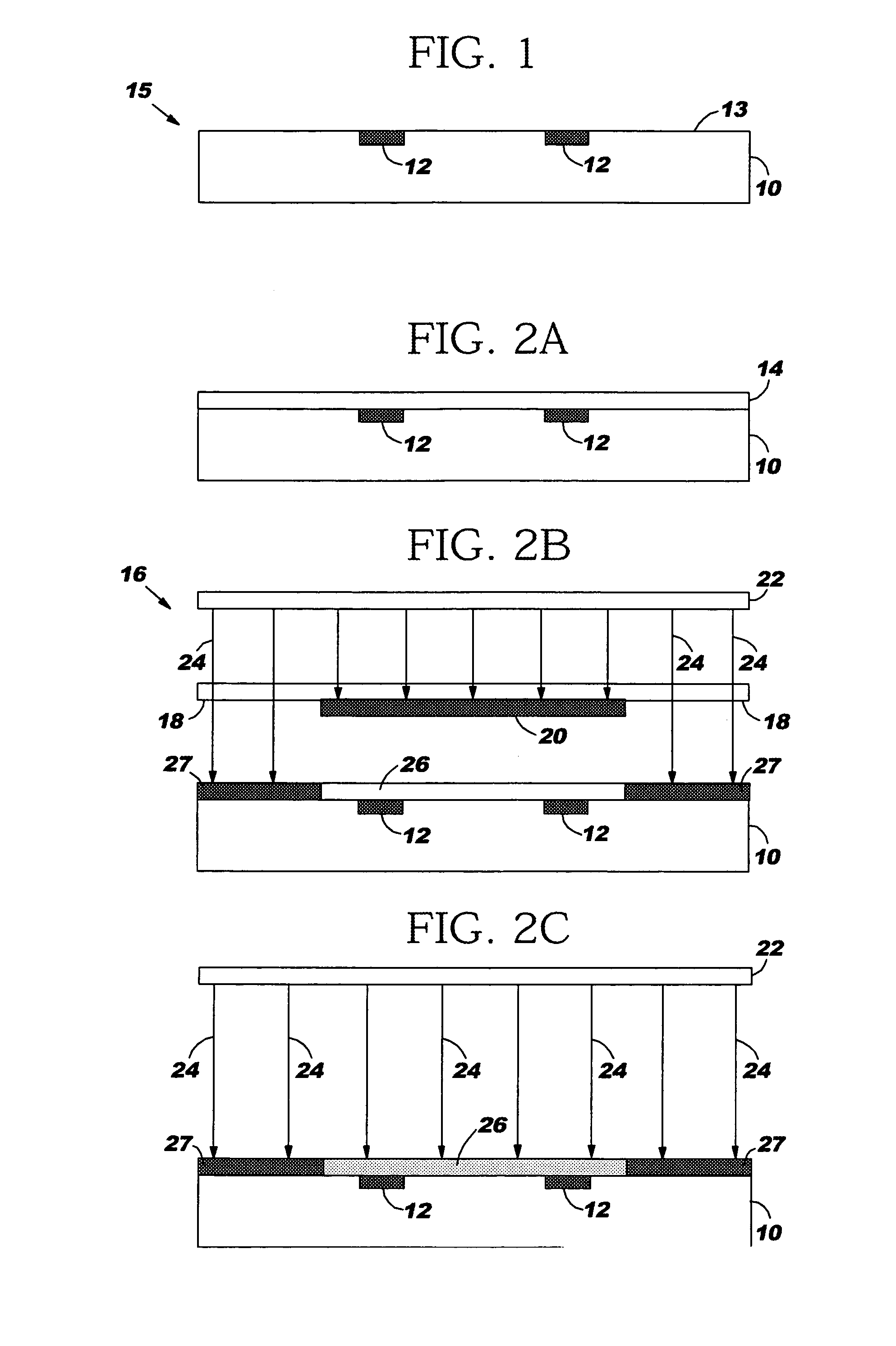
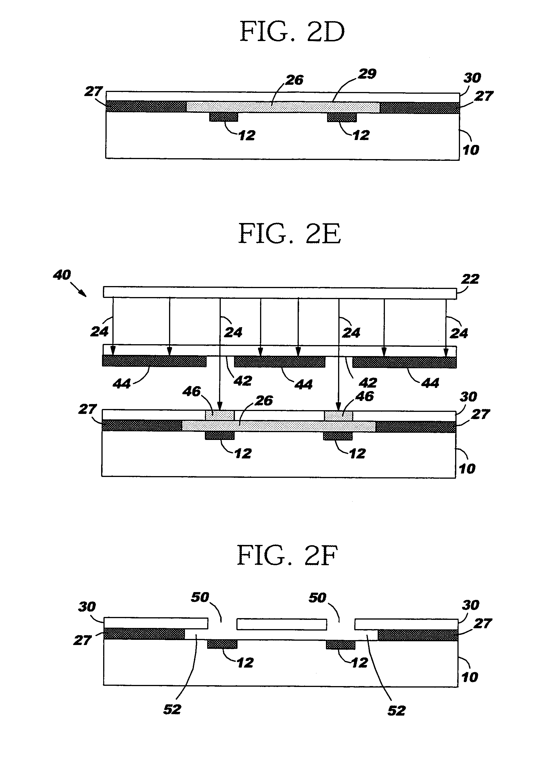
Thereafter, energy rays expose the protected area to weaken its composition for later removal.

Method used


Image

  • Inkjet printhead nozzle plate
  • Inkjet printhead nozzle plate
  • Inkjet printhead nozzle plate

Examples


Embodiment Construction

[0025]In the following detailed description of the preferred embodiments, reference is made to the accompanying drawings that form a part hereof, and in which is shown by way of illustration, specific embodiments in which the inventions may be practiced. These embodiments are described in sufficient detail to enable those skilled in the art to practice the invention, and it is to be understood that other embodiments may be utilized and that process or other changes may be made without departing from the scope of the present invention. The following detailed description is, therefore, not to be taken in a limiting sense and the scope of the present invention is defined only by the appended claims and their equivalents. In accordance with the present invention, an inkjet printhead having a nozzle plate formed of two positive resist layers in a sequence of exposure, heating and removal processing steps is hereinafter described.

[0026]With reference to FIG. 3, and appreciating that an in...


PUM


Abstract

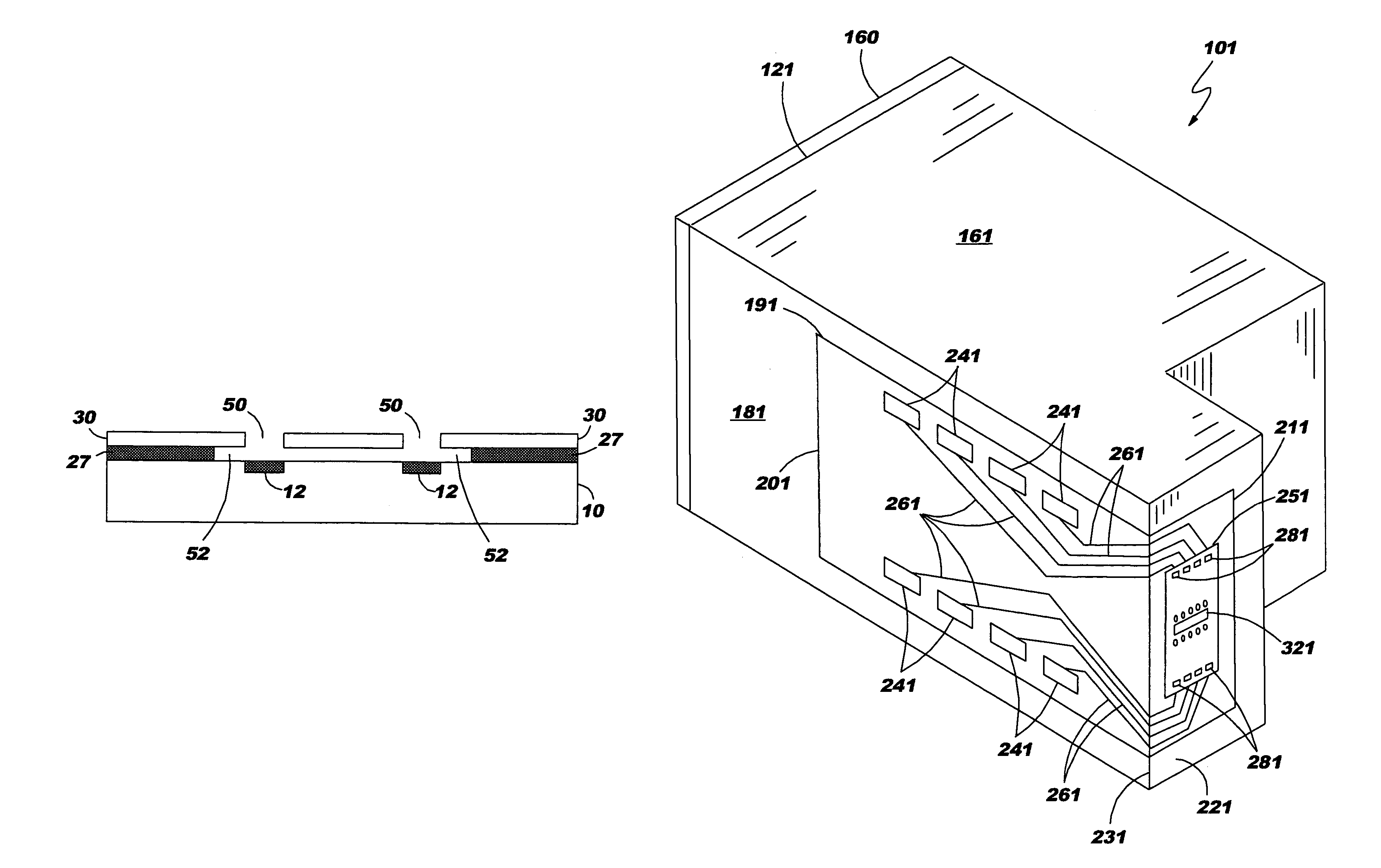
Methods of forming a nozzle plate include forming a first reverse imageable positive photoresist layer on the substrate and protecting an area thereof adjacent an ink ejection element from ultraviolet energy while exposing other than the protected area to such energy. Thereafter, the non-protected area is rendered insoluble by heating. Thereafter, the protected area is exposed to ultraviolet energy to weaken its structure for later removal. A second reverse imageable positive resist layer gets formed on the first layer and exposed to ultraviolet energy in a region directly above the ink ejection element. In a single step, both the protected area of the first layer and the non-protected region of the second layer are removed to form an ink flow feature, a bubble chamber or an orifice of the nozzle plate. The remainders of the first and second layers become blanket exposed to ultraviolet energy and cured in place.

Description

[0001]This application claims priority and benefit as a divisional application of U.S. patent application Ser. No. 10 / 422,153 filed on Apr. 24, 2003, now U.S. Pat. No. 6,773,869.FIELD OF THE INVENTION[0002]The present invention relates to inkjet printheads. In particular, it relates to a nozzle plate thereof formed with at least two positive photoresist layers that undergo a single removal of unwanted photoresist materials.BACKGROUND OF THE INVENTION[0003]The art of inkjet printing is relatively well known. In general, an image is produced by emitting ink drops from a printhead at precise moments such that they impact a print medium at a desired location. The printhead is supported by a movable print carriage within a device, such as an inkjet printer, and is caused to reciprocate relative to an advancing print medium and emit ink drops at times pursuant to commands of a microprocessor or other controller. The timing of the ink drop emissions corresponds to a pattern of pixels of th...

Claims


Application Information

Patent Timeline
IPC IPC(8): B41J2/015B41J2/16
CPCB41J2/162B41J2/1628B41J2/1629B41J2/1631B41J2/1642B41J2/1646B41J2/1433
Inventor PATIL, GIRISH S.
Owner FUNAI ELECTRIC CO LTD
Learn More