Piston vibratory pump

a technology of vibrating pump and piston pump, which is applied in the field of pumps, can solve the problems of not providing the range of pumping flow rate desired with a minimum of expense, and achieve the effect of effectively drawing fluid into or expulsion fluid, and increasing the efficiency of the mechanism

Inactive Publication Date: 2008-04-08
LISHANSKI GRIGORI +1
View PDF3 Cites 33 Cited by
  • Summary
  • Abstract
  • Description
  • Claims
  • Application Information

AI Technical Summary

Benefits of technology

The present invention provides an improvement on existing vibrating mechanisms that work by moving back and forth inside a chamber to create vacuums that bring fluids into the chamber and push them out again. To make this process more efficient, the invention adds a connecting tube that allows the pressure produced by the moving parts to help pull the fluids deeper into the chamber and force them out.

Problems solved by technology

The technical problem addressed in this patent text is the need for a pumping mechanism that can provide a wide range of pumping flow rates with a low cost and adaptable mechanism. The existing vibratory pump mechanisms have improved in this area, but there is still room for further improvement to increase their usefulness and efficiency over a wide range of potential uses.

Method used


Image

  • Piston vibratory pump
  • Piston vibratory pump
  • Piston vibratory pump

Examples


Embodiment Construction

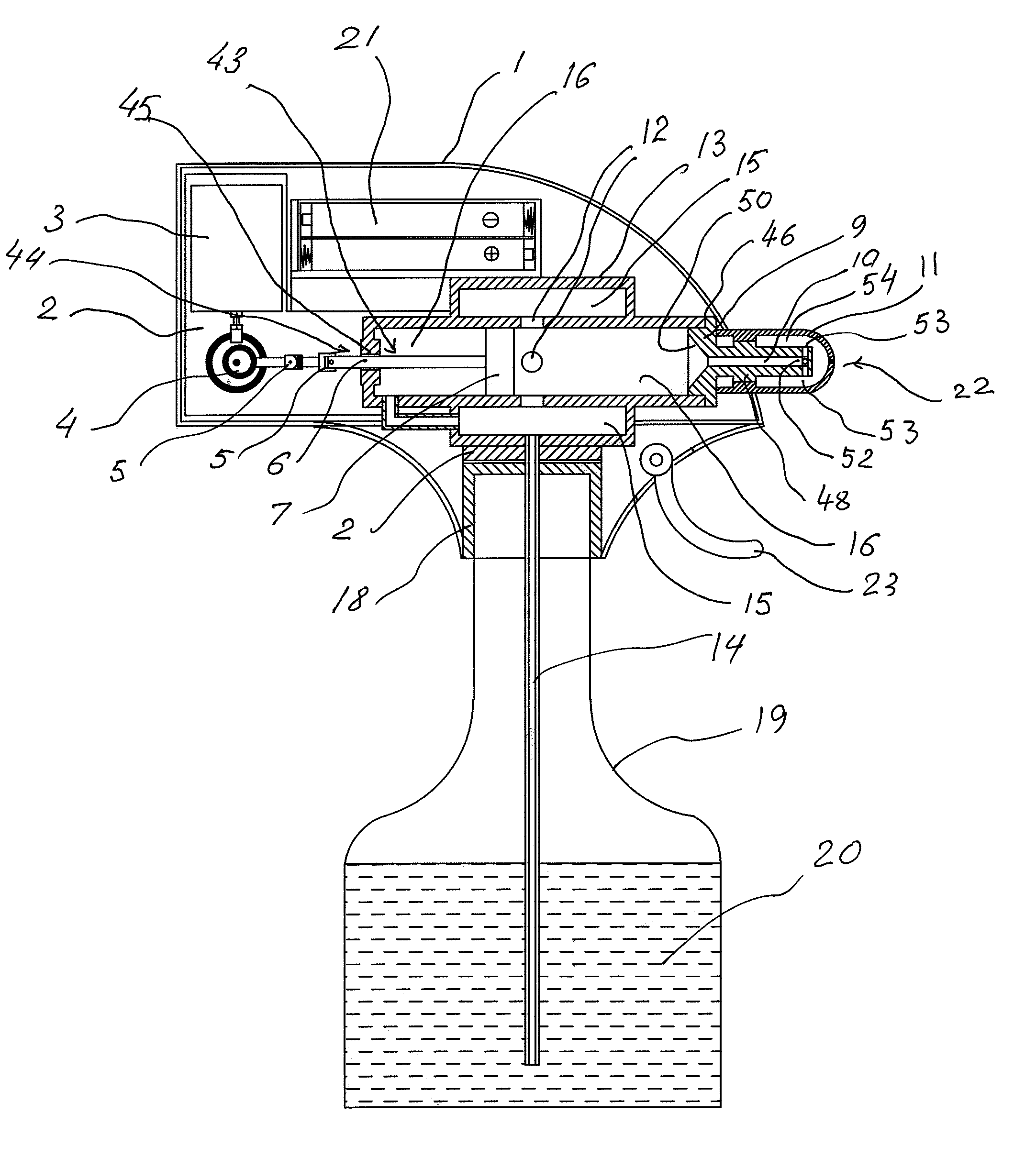
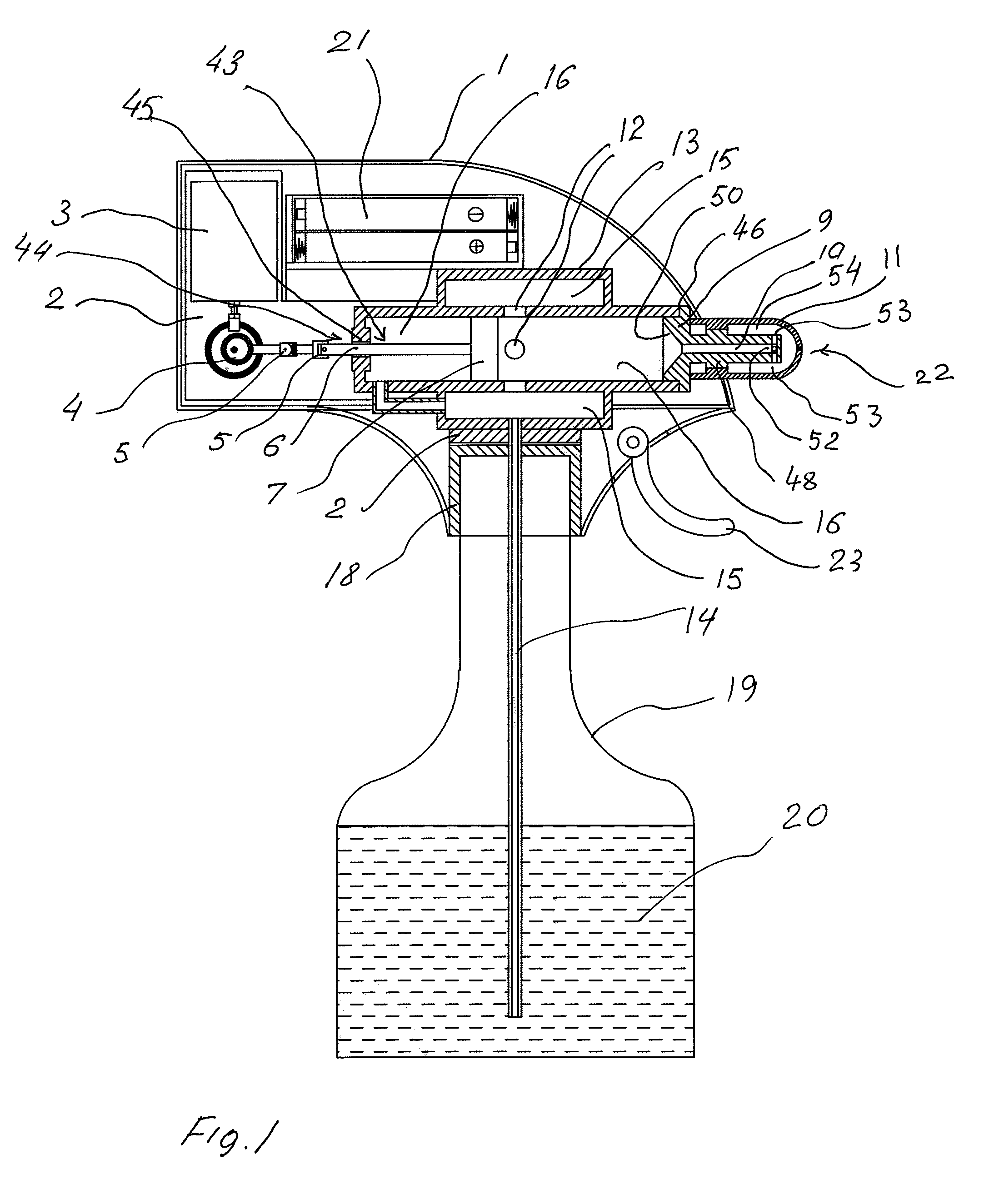
[0013]With reference now to the drawing figures in which like reference numerals designate like parts throughout the disclosure, a pumping mechanism constructed according to the present invention is indicated generally at 2 in FIG. 1. The mechanism 2 is contained within a housing 1 that includes a coupling 18 releasably attachable to a fluid reservoir or bottle 19. The bottle 19 includes an amount of a fluid 20 that is to be dispensed by the mechanism 2. However, the housing 1 enclosing the mechanism 2 can take various forms, including those not directly connected to the reservoir as shown in the drawing figures.

[0014]The mechanism 2 includes a motor 3 operatively connected to a power supply 21, preferably formed by a pair of batteries, but can be any suitable power supply. The connection between the motor 3 and power supply 21 is controllable by a suitable switch, and preferably a manually operated handle 23 in order to enable the power supply 21 to operate the motor 3. When operat...


PUM


Abstract

The present invention is an improved vibratory pumping mechanism that increases the efficiency of utilization of the vibratory motion within a mechanism. More specifically, the mechanism includes a central chamber within which a piston is oscillated to draw fluid into the chamber and expel fluid from within the chamber outwardly through a nozzle connected to the chamber. The chamber includes a pressure tube connected to a rearward end of the chamber and to a secondary chamber positioned around and in fluid communication with the chamber. The pressure tube allows the negative pressure generated by the motion of the piston in either direction to be utilized in preventing any fluid from being directed out of the mechanism in a direction other than through the nozzle, thereby increasing the efficiency of the pump.

Description


Claims


Application Information

Patent Timeline
Owner LISHANSKI GRIGORI
Why Eureka
Try Eureka