Light emitting apparatus for medical applications

a technology of light-emitting equipment and medical applications, which is applied in the field of semiconductor-based light-emitting equipment for medical applications, can solve the problems of increased heat generation, difficulty in light-emitting, lack of efficient and convenient light-emitting methods, etc., and achieves efficient light-emitting means, high drive current, and high intensity

Active Publication Date: 2008-04-08
BWT PROPERTY
View PDF6 Cites 43 Cited by
  • Summary
  • Abstract
  • Description
  • Claims
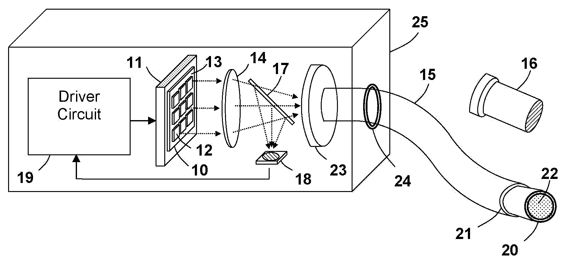
  • Application Information

AI Technical Summary

Benefits of technology

[0007]It is thus the goal of the present invention to provide a high intensity light emitting apparatus with efficient light energy delivery means for photo-dynamic-therapy (PDT), photobiostimulation (photobiomodulation), photo-sterilization, photo-curing, and other medical applications.
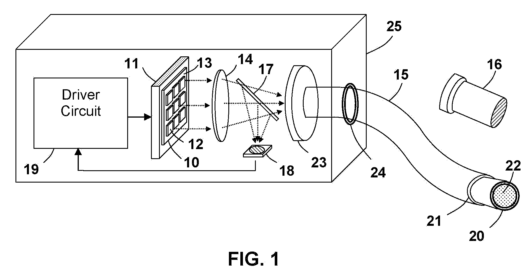
[0008]According to one aspect of the present invention, the light emitting apparatus comprises a high intensity LED (LED array) that adopts a COB package, where the LED chips are directly surface mounted on a thermal conductive substrate. The COB package allows much higher drive currents to be applied on the LED chips as well as greatly improved packing densities in comparison with traditional T-pack low power LEDs (LED arrays). As a result, the disclosed light emitting apparatus can produce a light intensity of >1,000 mW / cm^2. The light emitting apparatus is also capable to operate in a pulsed mode with peak light intensity in the range of several thousand mW / cm^2 to further enhance its treatment result. The output intensity of the light emitting apparatus can be electronically controlled to adapt for both low intensity and high intensity applications.
[0009]According to another aspect of the present invention, the light emitting apparatus comprises a flexible liquid light guide for light energy delivery. The flexible liquid light guide, formed by a plastic tube filled with transparent, high refractive index liquid, is used as a hand piece separated from the LED array. Thus the LED array can be mounted in the main console of the light emitting apparatus for improved heat dissipation. In addition, the liquid light guide features an acceptance angle three times larger than that of standard fiber light guides and a core size comparable to the surface area of the COB LED (LED array), which result in a high LED to waveguide coupling efficiency. The heat generation problem is avoided as the light source is positioned a distance away from the treatment site.

Problems solved by technology

However, these LEDs (LED arrays) also bring the problem of increased heat generation and difficulty in light energy delivery due to their large light emitting area and beam divergence angle.
The lack of an efficient and convenient light energy delivery method is a common weakness for the previous disclosed medical light emitting apparatus.
This is inconvenient for some hard-to-reach areas due to the size limitation of the LED array and its supportive components (such as lenses, heat sinks, etc.).
More importantly, the heat produced by the LED array will induce significant temperature increase for the treatment site in close contact.
This design is not suitable for high intensity LEDs (LED arrays) as the hand-held device can not provide efficient heat dissipation for the high intensity LEDs.
In addition, the fiber optic light guide suffers a filling factor and hot spot issue as it is generally composed of a plurality of optical fibers bundled together where there exist both bright and dark regions when illuminated.

Method used


Image

  • Light emitting apparatus for medical applications
  • Light emitting apparatus for medical applications

Examples


Embodiment Construction

[0013]Before describing in detail embodiments that are in accordance with the present invention, it should be observed that the embodiments reside primarily in combinations of method steps and apparatus components related to a light emitting apparatus for medical applications. Accordingly, the apparatus components and method steps have been represented where appropriate by conventional symbols in the drawings, showing only those specific details that are pertinent to understanding the embodiments of the present invention so as not to obscure the disclosure with details that will be readily apparent to those of ordinary skill in the art having the benefit of the description herein.

[0014]In this document, relational terms such as first and second, top and bottom, and the like may be used solely to distinguish one entity or action from another entity or action without necessarily requiring or implying any actual such relationship or order between such entities or actions. The terms “co...


PUM


Abstract

A light emitting apparatus is disclosed for medical applications including photo-dynamic-therapy (PDT), photobiostimulation (photobiomodulation), photo-sterilization, and photo-curing. The light emitting apparatus comprises a plurality of semiconductor light emitting elements, preferably light emitting diodes (LEDs) to produce a high intensity light beam, and a liquid light guide for delivering the light beam from the light source to the treatment site.

Description

REFERENCE TO RELATED APPLICATIONS[0001]This application claims an invention which was disclosed in Provisional Patent Application No. 60 / 596,802, filed Oct. 21, 2005, entitled “Light Emitting Apparatus for Medical Applications”. The benefit under 35 USC §119(e) of the above mentioned United States Provisional Applications is hereby claimed, and the aforementioned application is hereby incorporated herein by reference.FIELD OF THE INVENTION [0002]This invention generally relates to a light emitting apparatus and more specifically to a semiconductor light emitting apparatus for medical applications.BACKGROUND[0003]Semiconductor light emitting apparatus, preferably light emitting diodes (LEDs), are considered to be an ideal candidate for photo-dynamic-therapy (PDT), photobiostimulation (photobiomodulation), photo-sterilization, photo-curing, and other medical applications due to their long lifetime, high wall-plug efficiency, and low heat generation.[0004]Some examples of prior arts re...

Claims


Application Information

Patent Timeline
Patent Type & Authority Patents(United States)
IPC IPC(8): G01J1/04A61B1/07
CPCA61C19/003A61N5/062G01J1/02G01J1/0252G01J1/32A61N2005/063A61N2005/0652G01J1/0407
Inventor WANG, SEAN XIAOLU
Owner BWT PROPERTY
Why Eureka
Try Eureka