Moving object monitoring surveillance apparatus for detecting, tracking and identifying a moving object by zooming in on a detected flesh color

a technology for monitoring surveillance and moving objects, applied in the field of surveillance equipment, can solve the problems of destroying the sharpness of the face image, affecting the detection effect, and affecting the detection effect, and achieve the effect of partially enlarged images of moving objects

Active Publication Date: 2008-04-08
NIPPON MICRO SYST
View PDF3 Cites 110 Cited by
  • Summary
  • Abstract
  • Description
  • Claims
  • Application Information

AI Technical Summary

Benefits of technology

[0004]The video camera device sequentially monitors at least one single surveillance area. A single apparatus thus monitors a wide surveillance area. The video camera device includes a CCD camera. With the CCD camera incorporated, compact design is implemented, and RGB signal is acquired on a per pixel basis. Subsequent process becomes easy. Since the CCD camera includes a zoom lens controlled by the CPU, the image of the moving object may be partially enlarged.
[0005]In accordance with the present invention, a whole body tracking mode is available. The CPU retrieves the frame data stored in th...

Problems solved by technology

If the CCD camera is used to monitor a person, the face of the person becomes too small and sharpness of the face image is destroyed.
It is difficult to identify the person....

Method used


Image

  • Moving object monitoring surveillance apparatus for detecting, tracking and identifying a moving object by zooming in on a detected flesh color
  • Moving object monitoring surveillance apparatus for detecting, tracking and identifying a moving object by zooming in on a detected flesh color
  • Moving object monitoring surveillance apparatus for detecting, tracking and identifying a moving object by zooming in on a detected flesh color

Examples


Embodiment Construction

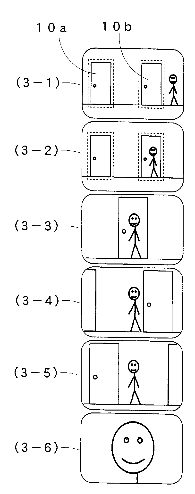
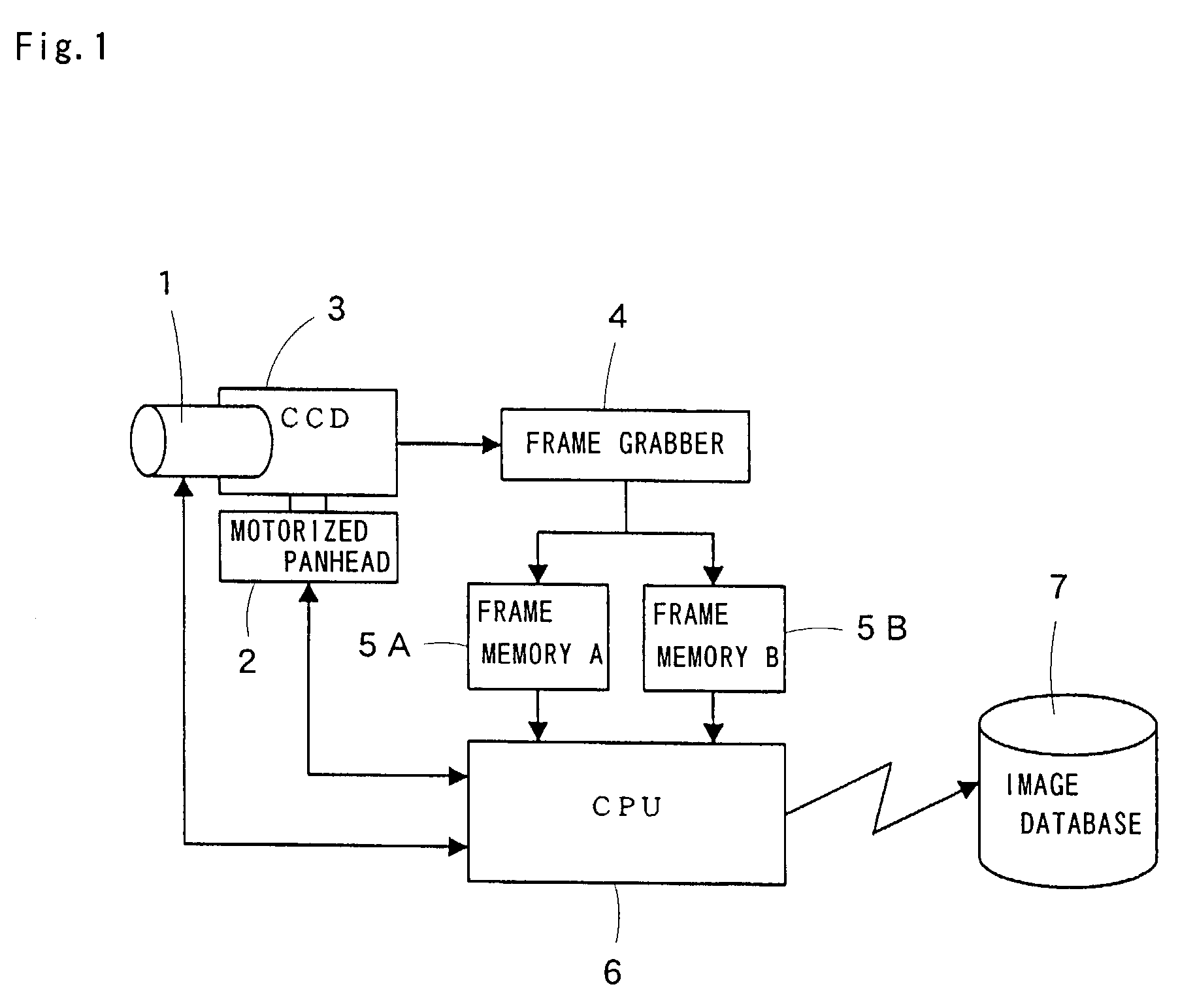
[0019]The preferred embodiments of the present invention will now be discussed with reference to the attached drawings. FIG. 1 is a block diagram of a moving object monitoring surveillance apparatus of the present invention. A zoom lens 1 continuously varies the focal length thereof, a motorized panhead 2 is motor driven for panning and tilting operations, and a CCD camera 3 converts an image taken by the zoom lens 1 into a video signal. The moving object monitoring surveillance apparatus thus constructed monitors a predetermined area, and tracks a moving object using the motorized panhead 2 if the moving object enters the predetermined area, and zooms in and out the moving object using the zoom lens 1. A frame grabber 4 receives the video signal into which the CCD camera 3 converts the image, and selectively transfers the video signal to memories at a subsequent stage. Frame memories 5A and 5B, mutually identical to each other and arranged in parallel, receive and store the video s...


PUM


Abstract

A moving object monitoring surveillance apparatus that controls a camera using a motorized panhead and a motorized zoom lens to identify correctly a moving object, particularly, a person is disclosed. The apparatus includes a video device acquiring information of the image of a moving object as a video signal, a panhead for panning and tilting the video device, a frame grabber for extracting, frame by frame, a still image from the video signal output from the video device and binarizing the still image into frame data, a plurality of frame memories for alternately storing the binarized frame data, a CPU for controlling the operation of the panhead and for processing the frame data, and an image database for storing the processed data. The video device sequentially monitors at least one single surveillance area. The CPU compares frame data with immediately prior frame data to determine a difference therebetween, tracks coordinates corresponding to the difference if the difference is detected, and detects and expands a particular color.

Description

FIELD OF THE INVENTION[0001]The present invention relates to a surveillance apparatus for monitoring a moving object employing an optical lens or lenses and a solid-state camera using Charge Coupled Device (hereinafter said CCD camera) and, more particularly, to an apparatus which extracts the face of a person who enters a surveillance area and captures the image of the face of the person.PRIOR ART[0002]Means for monitoring a moving object using a CCD camera and recording the image of the object in a magnetic tape is known. During this use, the CCD camera focuses on a moving object with lenses in front of the CCD camera. If a surveillance area is widened using a wide-angle lens, the percentage of the area of the moving object to the entire frame becomes relatively small. If the CCD camera is used to monitor a person, the face of the person becomes too small and sharpness of the face image is destroyed. It is difficult to identify the person. Conversely, if a telephoto lens is used t...

Claims


Application Information

Patent Timeline
IPC IPC(8): H04N7/18G08B13/196H04N5/225H04N5/222H04N5/232
CPCH04N7/188
Inventor YAMAZAKI, SADAHIKOTANIBUCHI, KOUICH
Owner NIPPON MICRO SYST
Why Eureka
Try Eureka