
Apparatus and method for reading out a differential capacity with a first and second partial capacity

a differential capacity and differential capacity technology, applied in the field can solve the problems of inability to secure readout of fast changes in capacity which occur for a short time during the transient state, inability to use continuous readout with high accuracy, and inability to use specific problems or only restrictions, etc., to achieve the effect of reducing the number of times of differential capacity reading, and reducing the number of differential capacity readings

Inactive Publication Date: 2008-04-08
FRAUNHOFER GESELLSCHAFT ZUR FOERDERUNG DER ANGEWANDTEN FORSCHUNG EV
View PDF13 Cites 36 Cited by
  • Summary
  • Abstract
  • Description
  • Claims
  • Application Information

AI Technical Summary

Benefits of technology

The present invention provides an apparatus and method for accurately reading the differential capacity of two partial capacities. The apparatus includes two oscillators, each connected to a respective partial capacity, and a switching means for switching between the two oscillators. The method involves generating signals indicating the period duration of the oscillators and comparing them to each other to determine the difference in capacity between the two partial capacities. The invention allows for continuous detection and can detect both slow and rapid changes in capacity. The technical effects of the invention include improved accuracy in reading differential capacities and the ability to detect changes in capacity over time.

Problems solved by technology

Today many circuit variations are known for reading out differential capacities, which, however, cannot be employed for specific problems or only with restrictions.
However, the circuitry described above has the disadvantage that a continuous readout with high accuracy is not possible, because readout is not possible during a transient state of the oscillator.
In addition to this, a secure readout of fast changes in capacity which occur for a short time during the transient states is thus not possible.
However, the use of the voltage comparison means has the disadvantage that complicated calibrations are necessary to compensate charge injections caused by a switchover.

Method used


Image

  • Apparatus and method for reading out a differential capacity with a first and second partial capacity
  • Apparatus and method for reading out a differential capacity with a first and second partial capacity
  • Apparatus and method for reading out a differential capacity with a first and second partial capacity

Examples


Embodiment Construction

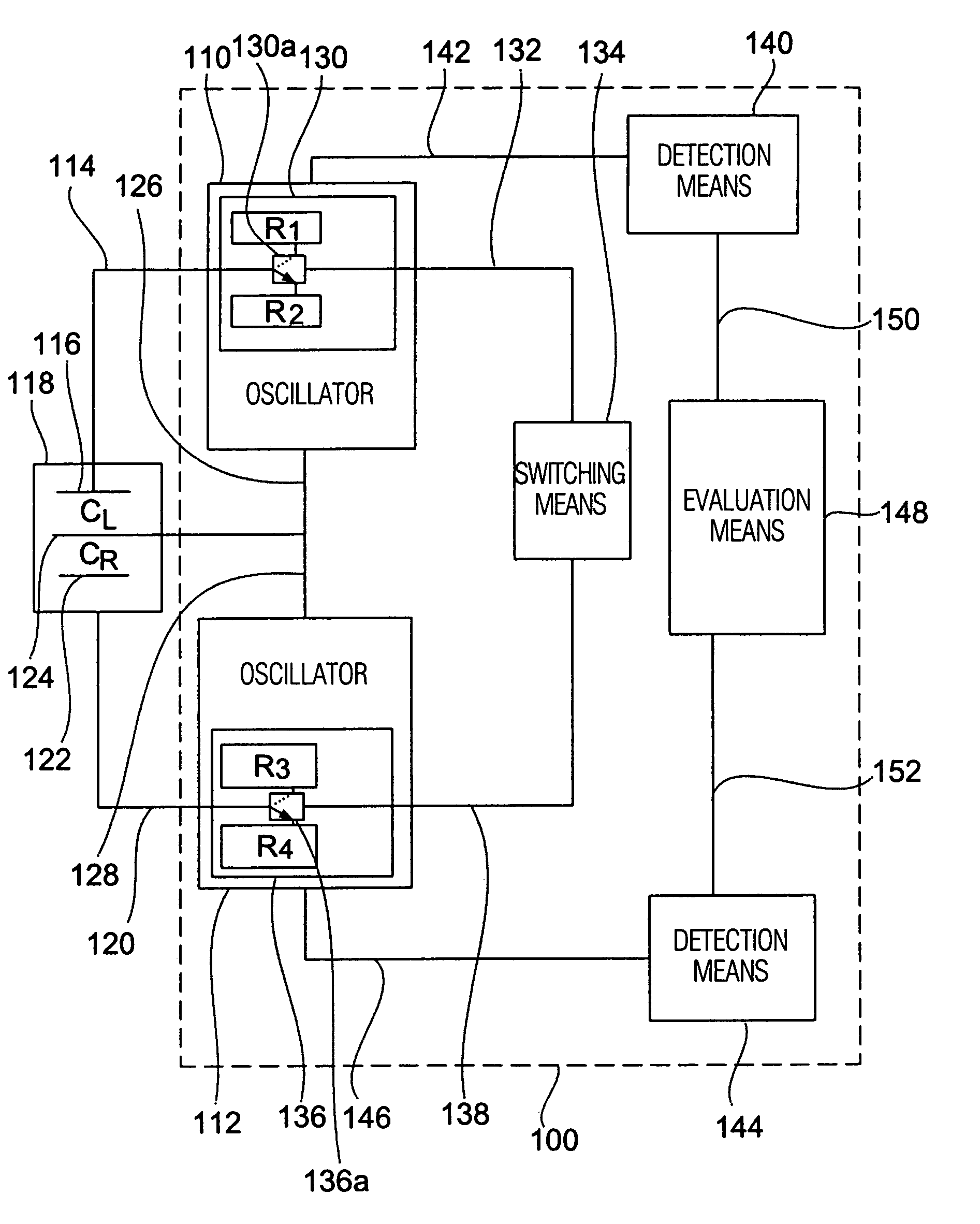
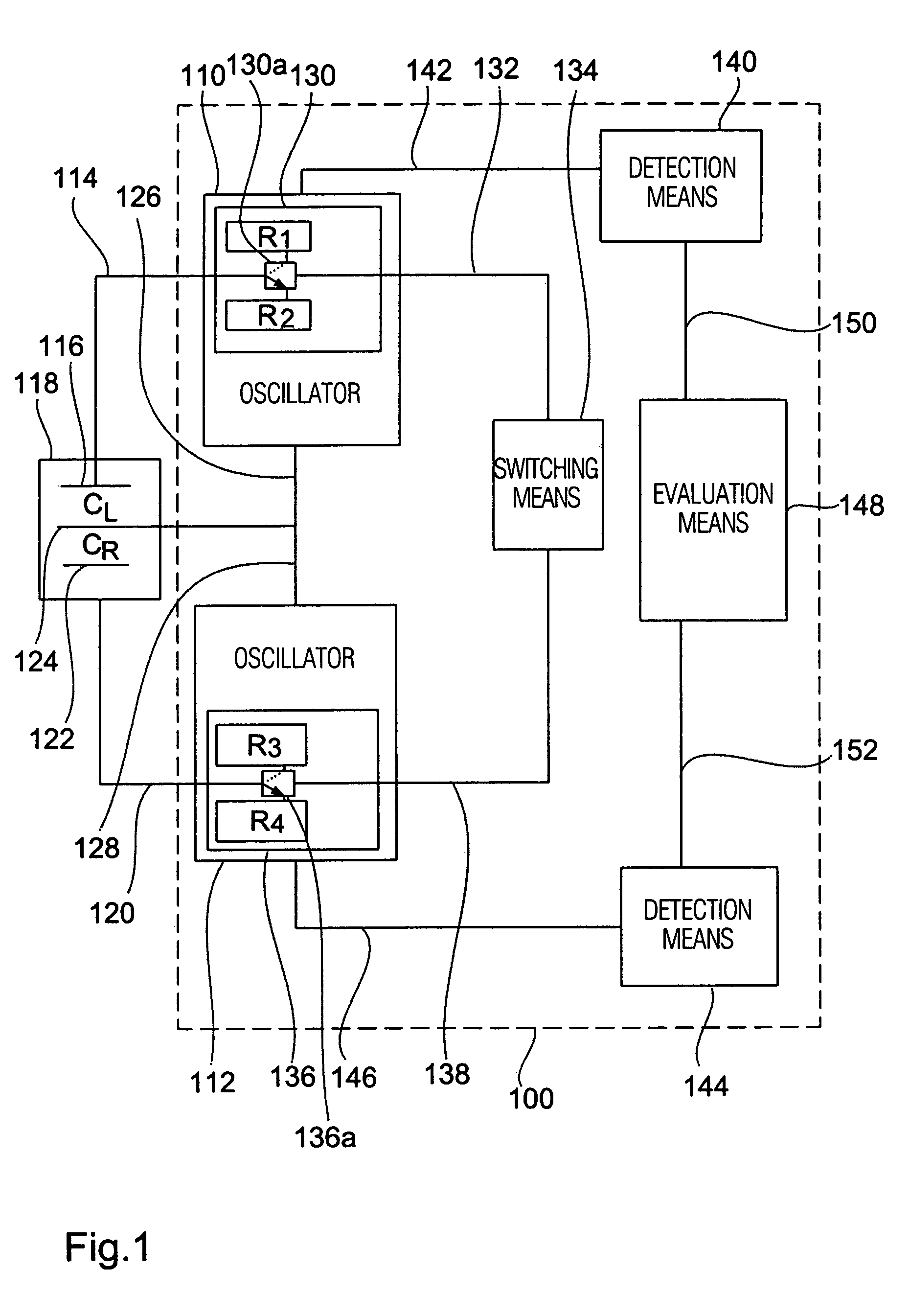
[0024]Referring to FIG. 1 a readout apparatus 100 is shown as a first embodiment of the present invention. The readout apparatus 100 comprises a first oscillator 110 and a second oscillator 112, the first oscillator 110 being connectable to a first fixed electrode 116 of a differential capacity 118 via a line 114, while the second oscillator 112 is connectable to a second fixed electrode 122 via a line 120. In one embodiment the first oscillator 110 and the second oscillator 112 each comprise a square-wave oscillator formed by a CMOS circuit.

[0025]The differential capacity 118 comprises a moveable electrode 124 connectable to the first oscillator 110 via a line 126 and to the second oscillator 112 via a line 128. The differential capacity 118 includes any known type, for example a semiconductor differential capacitor, which is formed by means of known etching and masking steps in a semiconductor substrate. For example, the differential capacity 118 includes a sensitive element of a ...


PUM


Abstract

An apparatus for reading out a differential capacity with a first and second partial capacity includes a first oscillator having a first frequency-determining element connectable to the first partial capacity and a second oscillator having a second frequency-determining element connectable to the second partial capacity; a switching means to switch the first frequency-determining element into a first state or to switch it into a second state, and to switch the second frequency-determining element into a third state or to switch it into a fourth state; read apparatus having a first detection means connected to the first oscillator; and an evaluation means which carries out a quotient formation to obtain a value indicating a quotient of the first and the second partial capacity.

Description

CROSS-REFERENCE TO RELATED APPLICATION[0001]This application is a continuation of copending International Application No. PCT / EP02 / 01857, filed Feb. 21, 2002, which was designated in the United States and was not published in English.BACKGROUND OF THE INVENTION[0002]1. Field of the Invention[0003]The present invention relates to reading out capacities and in particular to reading out differential capacities.[0004]2. Description of Prior Art[0005]Today in many apparatuses differential capacities are used as sensitive elements. For example, differential capacities are used as electrical elements on various sensors. Such sensors comprise, for example, acceleration sensors, pressure sensors or path sensors. Today many circuit variations are known for reading out differential capacities, which, however, cannot be employed for specific problems or only with restrictions.[0006]For example, in particular applications it is required to detect a relatively slow change in capacity with high re...

Claims


Application Information

Patent Timeline
Patent Type & Authority Patents(United States)
IPC IPC(8): G01R23/00G01D5/241
CPCG01D5/2417
Inventor NEHRIG, OLIVER
Owner FRAUNHOFER GESELLSCHAFT ZUR FOERDERUNG DER ANGEWANDTEN FORSCHUNG EV
Learn More