Method and monitoring device for the detection and monitoring of the contamination of an optical component in a device for laser material processing

Active Publication Date: 2013-10-03
JURCA MARIUS
View PDF11 Cites 15 Cited by
  • Summary
  • Abstract
  • Description
  • Claims
  • Application Information

AI Technical Summary

Benefits of technology

[0014]The goal of embodiments of the invention under consideration is to propose a method and a monitoring device to detect and monitor the contamination of an optical component in a device for laser material processing, with which the degree of contamination can be continuously detected reliably, quickly, and independent of output fluctuations

Problems solved by technology

In particular in beam shaping and deflection of high-power laser beams, the important thing is to always test the characteristics of the optical components used, such as lenses and mirrors, in the context of their functionality, since the high laser beam power density on the optical surfaces of the components can quickly lead to contamination, destruction, and to consequential damage.
Consequently, the optical component can sustain damage or even burst as a result of thermal stresses.
In particular, there may be a deformation due to the heating of the optical components, which can have a negative influence on the position of the focal point of the process laser beam in the TCP, so that aside from the output loss due to the burned-in spatters, an additional damage of the process quality may occur.
The known methods, however, have considerable disadvantages, which greatly limit a practical application.
For example, a desired change of the output power of the process laser leads to false alarm signals (with an increase in output) or to a loss of the monitoring function (with a diminution of the output, since the relatively small increase of the useful monitoring signal can lay under the alarm threshold).
The influence of the radiation of the process laser, reflected from the workpiece, is also uncontrolled.
Furthermore, this kind of device is not free of distu

Method used


Image

  • Method and monitoring device for the detection and monitoring of the contamination of an optical component in a device for laser material processing
  • Method and monitoring device for the detection and monitoring of the contamination of an optical component in a device for laser material processing
  • Method and monitoring device for the detection and monitoring of the contamination of an optical component in a device for laser material processing

Examples


Embodiment Construction

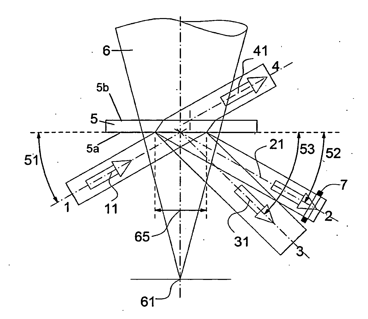
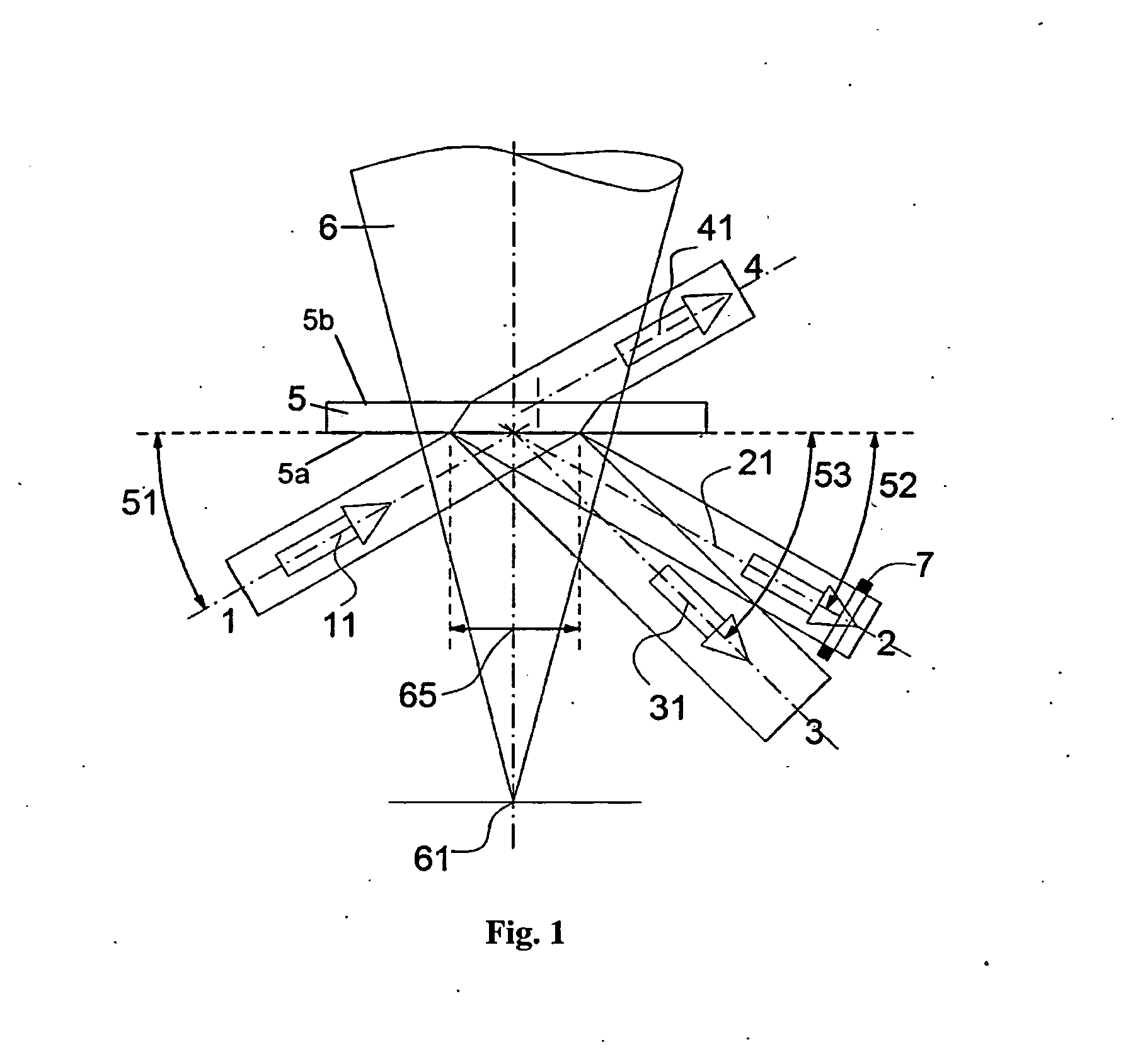
[0034]To implement the method in accordance with the invention, a monitoring device is used, as shown schematically in FIG. 1. This monitoring device is provided for incorporation into the processing head of a device for laser material processing. Such a processing head is shown in FIG. 6.

[0035]The processing head emits a process laser beam 6 through a protecting, optically transparent window 5, which protects the other optical components in the processing head against process-caused spatters 55. The protective window 5 is appropriately provided with an antireflective (AR) coating. The process laser beam 6 is focused in a focal point 61 (tool center point, TCP) on the surface of a specimen to be processed.

[0036]The monitoring device shown in FIG. 1 comprises a light source 1, for example, a light-emitting diode or a laser diode, that irradiates a preferably collimated measurement beam 11 onto a central area 65 of the optical surface 5a of the protective window 5, facing the process,...


PUM

PropertyMeasurementUnit
Angleaaaaaaaaaa
Wavelengthaaaaaaaaaa
Reflectionaaaaaaaaaa

Abstract

A method and device for the detection and monitoring of the contamination of an optical component in a device for laser material processing, which emits a process laser beam through or onto the optical component. A measurement beam emitted by a light source is projected under an angle of incidence onto an optical surface of the optical component. The beam reflected from the outer surface of the protective window under the angle of reflection corresponding to the angle of incidence is conducted through an aperture stop onto a first light-sensitive detector so as to record the intensity of the reflected beam. The intensity of the scattered radiation, scattered diffusely from the optical surface of the component under a scattering angle, is recorded by a second light-sensitive detector. The degree of the contamination of the component is determined from the recorded intensities of the reflected beam and the scattered radiation.

Description

CROSS REFERENCE TO RELATED APPLICATIONS[0001]This application claims priority under 35 U.S.C. §119 to German Patent Application No. 10 2012 102 785.4 filed 30 Mar. 2012, the entire contents of which are incorporated herein by reference.FIELD OF THE INVENTION[0002]The invention concerns a method and a monitoring device for the detecting and monitoring of the contamination of an optical component, such as a lens, a protective window or a mirror, in a device for laser material processing.BACKGROUND OF THE INVENTION[0003]The use of optical components in the industrial environment primarily requires intact and clean optical surfaces of these components. In particular in beam shaping and deflection of high-power laser beams, the important thing is to always test the characteristics of the optical components used, such as lenses and mirrors, in the context of their functionality, since the high laser beam power density on the optical surfaces of the components can quickly lead to contamina...

Claims


Application Information

Patent Timeline
IPC IPC(8): G01N21/95
CPCG01M11/005G01M11/0278B23K26/428G01N21/958G01N21/95G01N21/94B23K26/707
Inventor JURCA, MARIUS
Owner JURCA MARIUS
Why Eureka
Try Eureka