Forward rail mounted trigger module

a trigger module and forward rail technology, applied in the direction of cartridge extractors, butts, weapons testing, etc., can solve the problems of poor trigger capability or misfire, difficult or impossible linkage adjustment, and restricted disassembly options, etc., to shorten or shorten the overall length of the linkage and eliminate slack between the triggers

Inactive Publication Date: 2008-04-15
J & T MUNITIONS
View PDF13 Cites 67 Cited by
  • Summary
  • Abstract
  • Description
  • Claims
  • Application Information

AI Technical Summary

Benefits of technology

[0005]To accomplish these goals, the module comprises a mounting rail interface with a built in trigger assembly, complete with a grip, a safety mechanism, and fire selector switch (if included). A hinged linkage bar is attached to the trigger assembly and is directed through the module, towards the primary trigger, to which the linkage is clamped with a cam and roller assembly. The primary trigger is covered with access shielding and the butt stock of the weapon is replaced with a shorter butt stock and a rail mounted cheek rest is added to the weapon. An adjustment screw is provided to lengthen or shorten the overall length of the linkage and eliminate slack between the triggers. The hinge in the linkage bar is positioned coaxially with the disassembly pivot point of the weapon.

Problems solved by technology

However, there are a number of disadvantages with the modules in the prior art.
They tend to require extensive modification to the weapon to support the bull-pup module on the weapon and restrict the option of disassembling the weapon as the modules also tend to block the disassembly pivot point of the base long gun.
Any linkage adjustment tends to be difficult or impossible.
Positioning of the linkage on the primary trigger must also be exact, as the linkage merely pushes the trigger and misplacement and extra “play” in the linkage can lead to poor trigger capabilities or misfire.
While the prior art inventions accomplish their individual objectives, they do not describe a rail mounted trigger mechanism; nor do they feature a direct, in-line hinged linkage between the secondary and primary triggers allowing for field disassembly of the weapon without removing the module.

Method used


Image

  • Forward rail mounted trigger module
  • Forward rail mounted trigger module
  • Forward rail mounted trigger module

Examples


Embodiment Construction

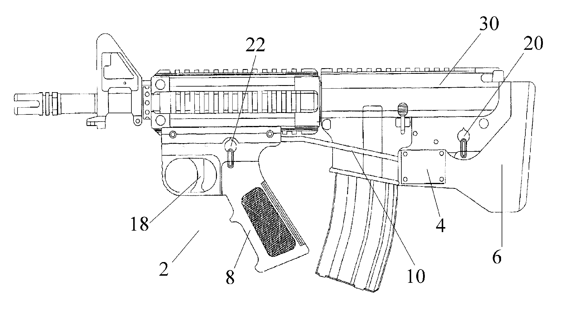
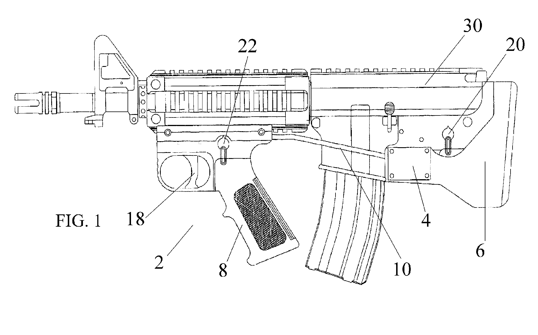
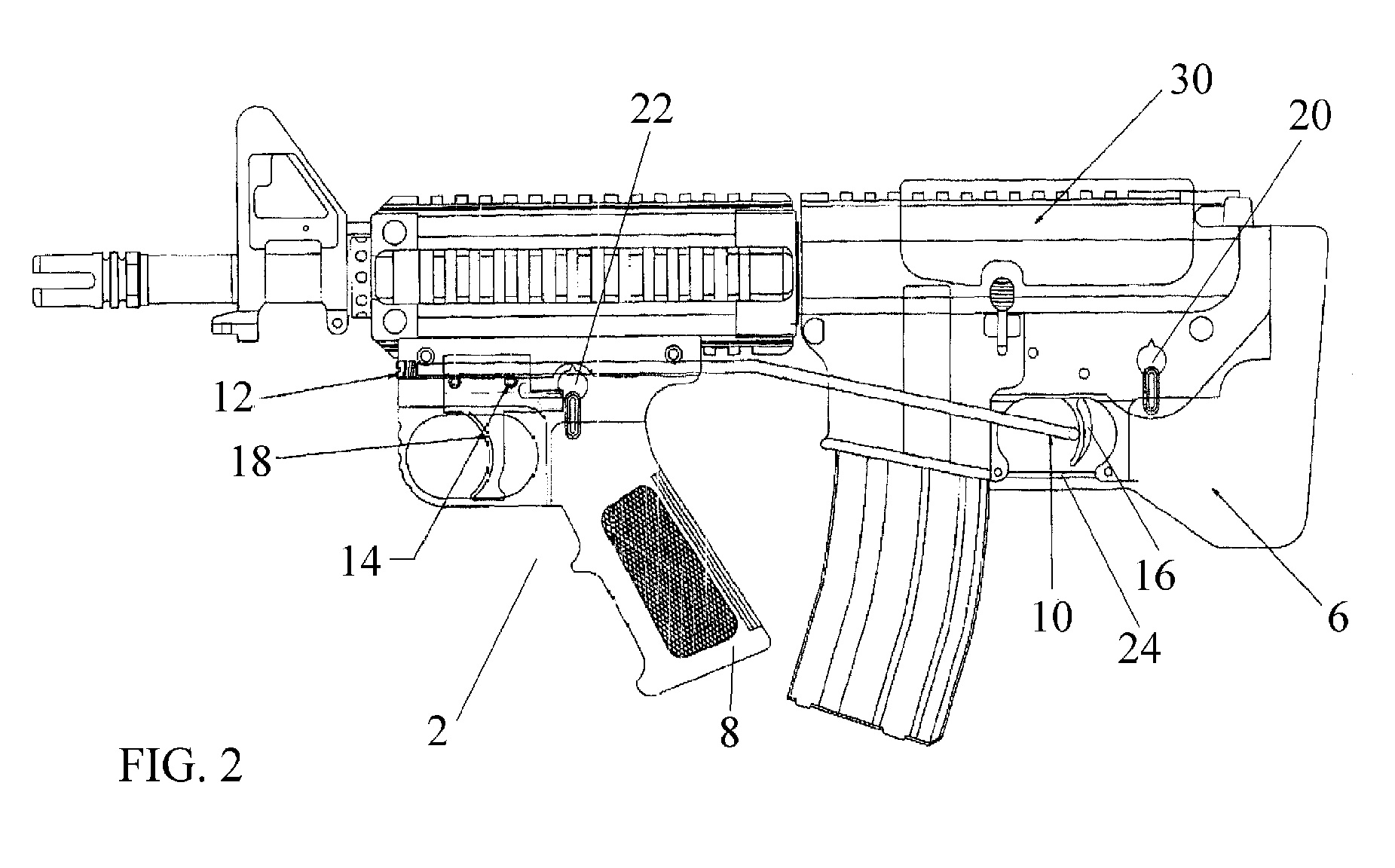
[0018]With reference now to the drawings, the preferred embodiment of the trigger module is herein described. The module, as seen in FIG. 1, for entire conversion, consists of 5 major components necessary to complete the weapon: a rail mounted trigger module 2, a pivoting linkage 10, a cam roller trigger actuator 28, a short butt stock 6 and a rail mount cheek rest 30. The first component is the trigger module 2. This includes the actual trigger mechanism so as to emulate the primary trigger 16 and surrounding area of the unmodified weapon. The trigger module 18 should include a safety mechanism 22 and, could possibly include the selector switch for semi-automatic rifles. The final component of the trigger module is the mounting component, located above the linkage 10 and trigger 18 components. This component may be a standard clamp-style interface for dove tail rails, which are standard for the industry and are usually mounted on the barrel, upper receiver and stock of a rifle. The...


PUM


Abstract

The present invention is a rail mounted forward trigger mechanism featuring in-line linkage between the primary and secondary triggers. Access to adjustment features provides adjustability while simultaneously allowing the mechanism to remain installed. The linkage is also hinged and mounted coaxially with the disconnect pivot point of a weapon, thereby allowing field stripping the weapon without removing the linkage. Connection to the primary trigger of the host weapon is ideally accomplished with a can and roller assembly for smoother and more controlled actuation. An electrical embodiment is also disclosed.

Description

FIELD OF INVENTION[0001]The present invention relates to improved gunstocks and firing mechanisms and more particularly relates to an attached module that locates a secondary trigger in front of the action of a firearm and allows for shortening the weapon by removal of the conventional stock, thereby allowing the weapon to be more compact and easier to handle and hold on target.BACKGROUND OF THE INVENTION[0002]Since firearms were developed, there have been many methods and devices developed for modifying a firearm and adapting such weapons to multiple use variations. One such variation is a shortening mechanism for a long gun, either rifle or shot gun, allowing it to be held on target easily and increase maneuverability and storage capabilities of the weapon. These devices, commonly called “bull-pups” typically involve installing a mechanism with a secondary trigger mounted so that the trigger is in front of the action of the weapon and mechanically linking the secondary and primary...

Claims


Application Information

Patent Timeline
Patent Type & Authority Patents(United States)
IPC IPC(8): F41A19/00
CPCF41A19/00F41C23/12F41C23/16F41C27/00
Inventor WEIR, ROBERT F.
Owner J & T MUNITIONS
Why Eureka
Try Eureka