Fluid control devices

a control device and fluid technology, applied in the direction of fluid pressure control, pressure relieving devices on sealing faces, instruments, etc., can solve the problems of reducing the performance in the presence of particulate matter, not pliable, and damage to the cutting capacity of high-speed fluid

Active Publication Date: 2008-04-15
EXXONMOBIL UPSTREAM RES CO
View PDF19 Cites 29 Cited by
  • Summary
  • Abstract
  • Description
  • Claims
  • Application Information

AI Technical Summary

Problems solved by technology

Operational challenges arise when the flow used to communicate pressure causes damage to the sealing element that is designed to maintain the desired pressure difference.
Damage can occur from the cutting capacity of high velocity fluid streams passing over a device's sealing component during the pressure maintenance operations required to continuously sustain the required differential pressure.
While these materials are durable, they are not pliable.
The lack of pliability results in reduced performance in the presence of particulate matter and reduced performance from surface imperfections on the sealing element or the component that the sealing element seals against, i.e., the seat.
For example, a steel ball could never seal a circular steel aperture if a sand grain was wedged between the steel ball and the edge of the aperture (or if the edge of the aperture was slightly nicked).
While the rubber ball is a superior sealing material, it is also highly susceptible to damage from the cutting action of high velocity fluid streams.
Thus, a technology gap exists for pressure metering applications that require high differential pressures, particulate insensitivity, and reliable repeatable operation.
For applications that require zero leak flow after a pressure differential is established and / or require cyclic operations, the use of rigid seal elements becomes inadequate.
ty. Valve designs that involve an isolated, or sealed, static pressure exhibit limited functionality in a downhole environm
epth. This change in static pressure results in a change in valve performance as a function of d
In addition, when valves are deployed downhole they are not readily accessible for servicing; thus significant expense is typically incurred during the downhole intervention activity.
These examples illustrate the inherent conflict between high differential pressure maintenance and reliable sealability in environments that may contain solid particles.

Method used


Image

  • Fluid control devices
  • Fluid control devices
  • Fluid control devices

Examples


example

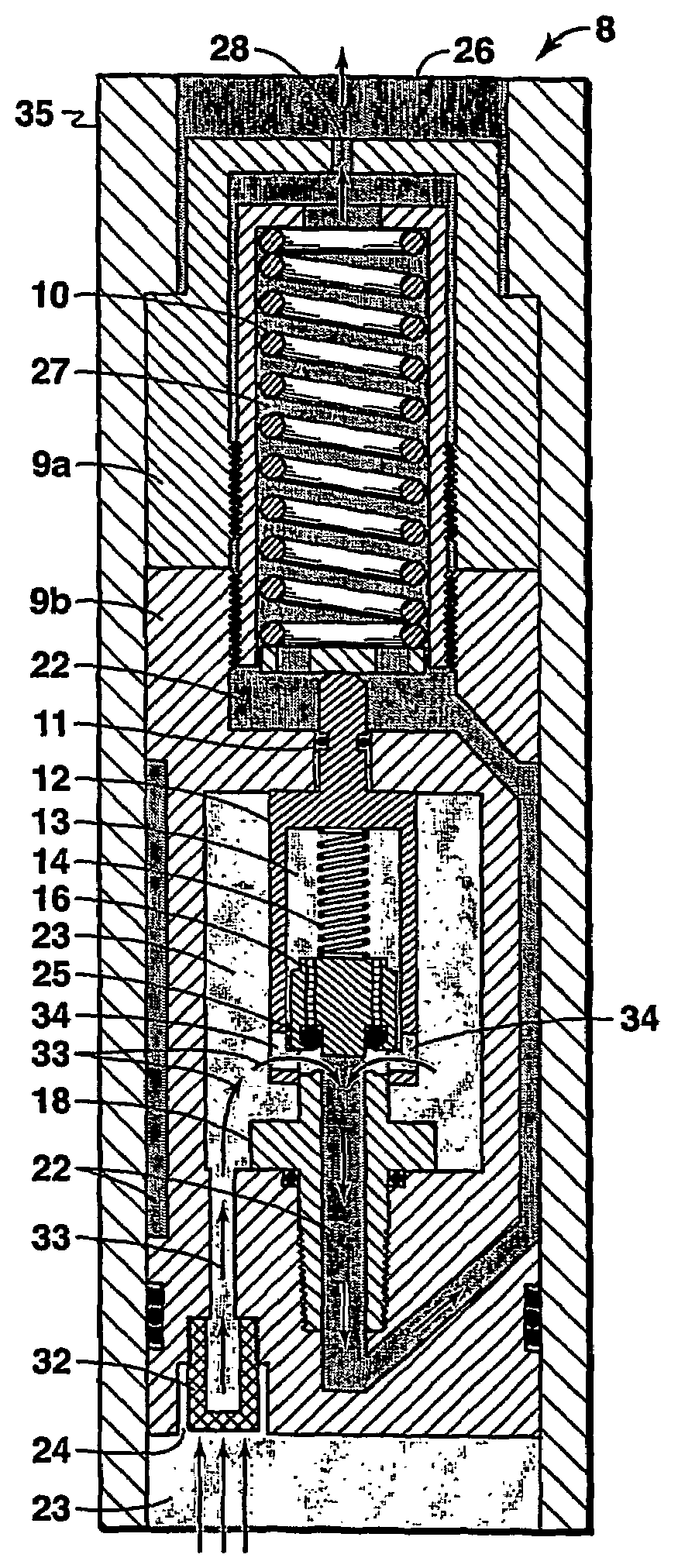
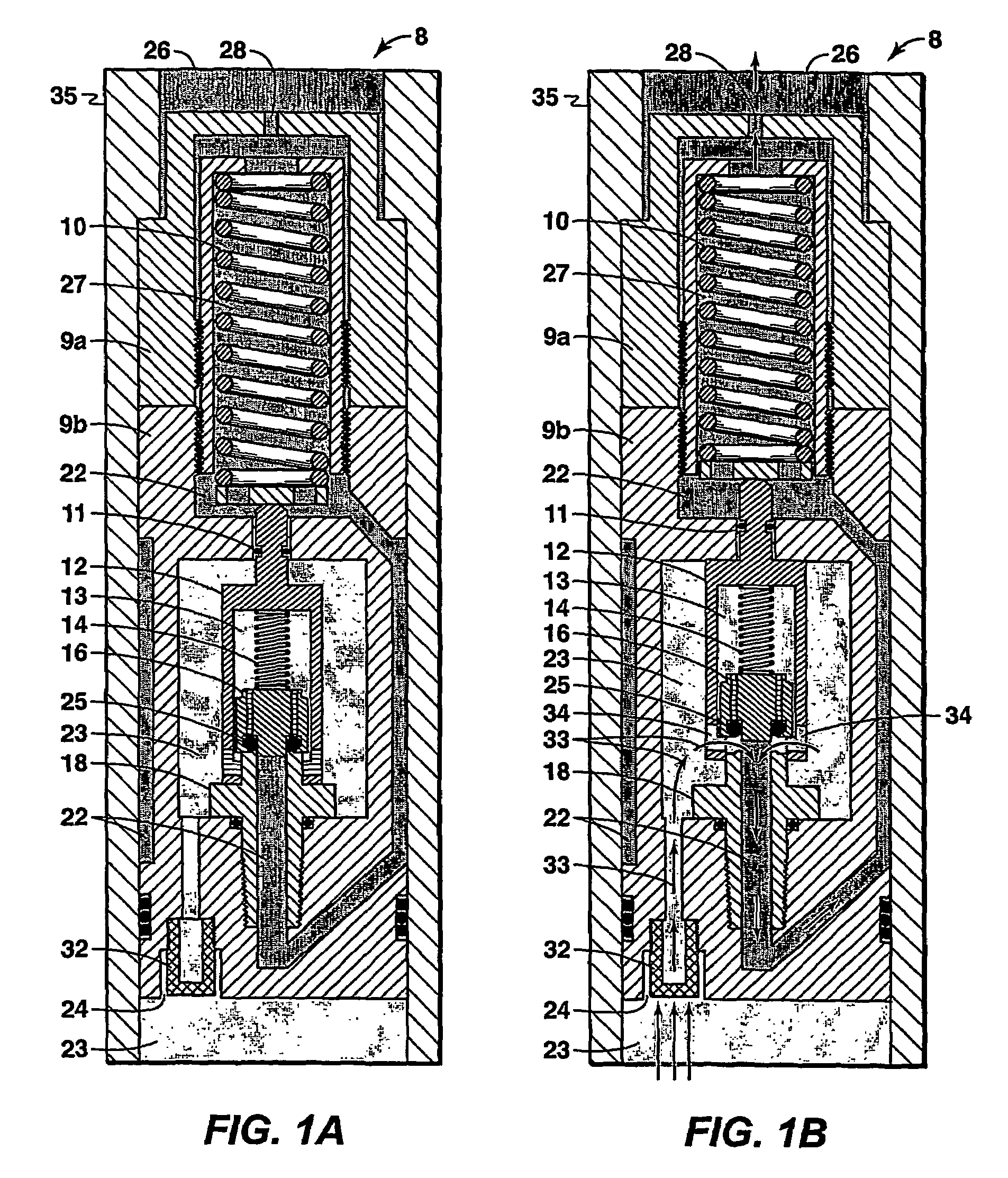
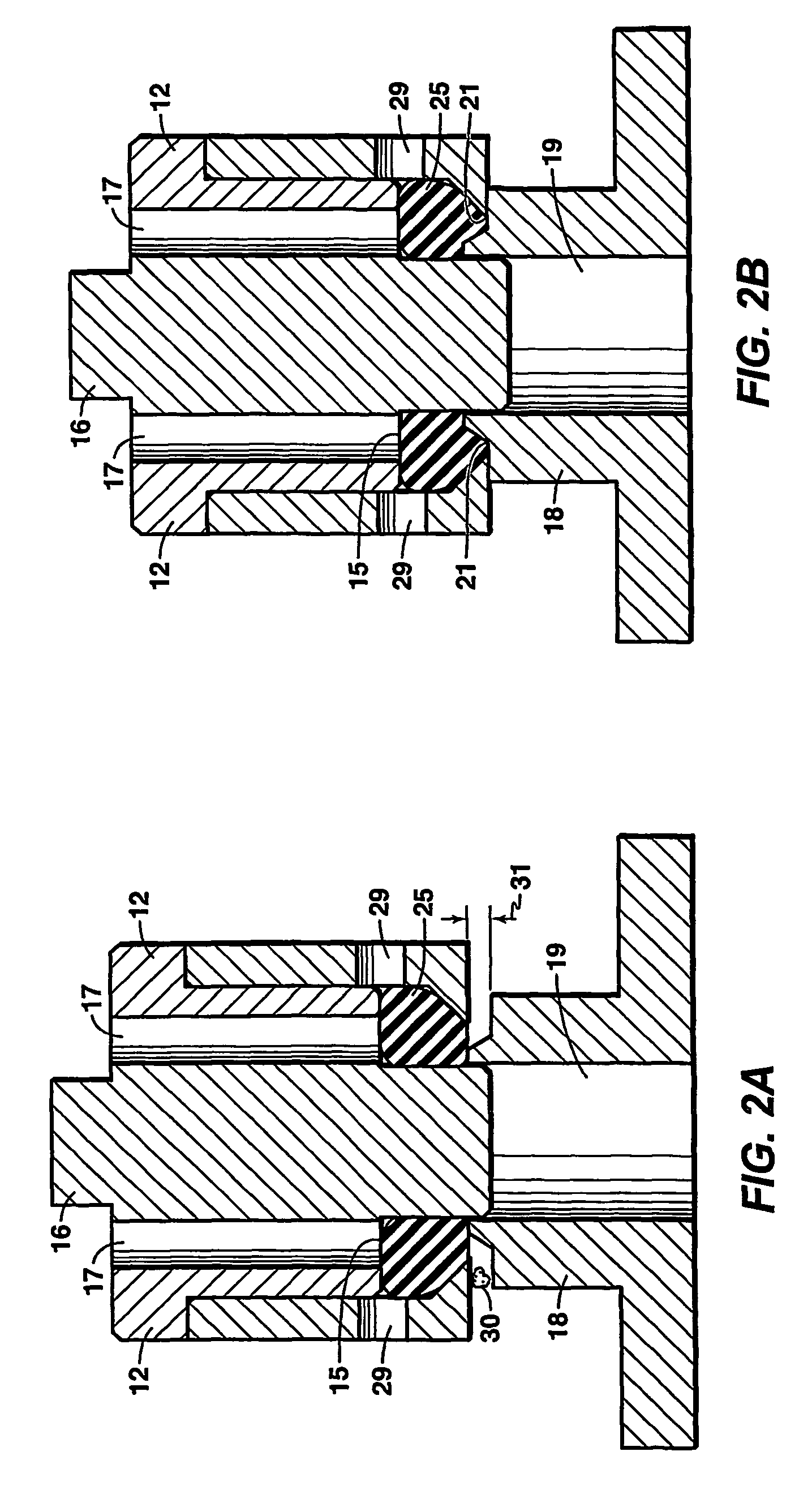
[0030]In this example, a fluid control device according to this invention is constructed by modification of a commercially available Circle Seal Controls Inc. (a division of CIRCOR) 5300 series pressure relief valve. Modifications include: (1) discarding the valve body and machining a new valve body that preserved the interior profile but altered the exterior geometry to reflect a cartridge valve style with the ability to flow axially through the valve or at a 90 degree angle to the valve axis; (2) modifying the valve from a three pressure system to a two pressure system by directing the exit flow into the spring cavity, thus changing the functionality to enable the valve to sense and actuate when the outlet pressure changes; (3) integrating an inlet filter into the valve body to allow fluid filtering to a particle size less than the seal mechanism design limit; (4) discarding the rigid Circle Seal 5300 poppet and replacing it with a specially designed poppet containing a pliable el...


PUM


Abstract

Improved fluid control devices are provided for metering pressure effectively in environments that may contain solid particles and in which the ambient pressure is subject to change. Such a valve comprises a valve body containing a plunger assembly contacting a first spring, said plunger assembly having a cavity and including a second spring and a poppet assembly engaged to said second spring within said cavity; and valve seat means located in position to contact said poppet assembly and essentially prohibit flow through the valve when fluid pressure at the valve inlet is less than a predetermined differential pressure plus a fluid pressure at the valve outlet.

Description

[0001]This application is the National Stage of International Application No. PCT / US04 / 029837, filed 14 Sep. 2004, which claims the benefit of U.S. Provisional Patent Application No. 60 / 503,019, filed 15 Sep. 2003.FIELD OF THE INVENTION[0002]This invention pertains to fluid control devices for metering, maintaining, and isolating fluid pressure and flow between two or more sources.BACKGROUND OF THE INVENTION[0003]Fluid control is routinely practiced within a wide variety of industries. Control is typically achieved using devices that are specifically designed to perform a unique control operation. Examples of such control devices are pressure relief valves, pressure regulators, back-pressure regulators, velocity fuses, mass flow controllers, pilot operated valves, check valves, and shuttle valves.[0004]Pressure is typically communicated from one source to another via the flow of a fluid such as gas or a liquid. Operational challenges arise when the flow used to communicate pressure ...

Claims


Application Information

Patent Timeline
Patent Type & Authority Patents(United States)
IPC IPC(8): F16K17/04F16K3/26G05D16/10
CPCF16K3/265F16K31/1225F16K31/363F16K31/383G05D16/103G05D16/109Y10T137/7783Y10T137/7835
Inventor LONNES, STEVEN B.
Owner EXXONMOBIL UPSTREAM RES CO
Why Eureka
Try Eureka