
Multi-label mailing form including certified self-mailer

a mailing form and label technology, applied in the field of mailing forms, can solve the problems of reducing the number of labels, so as to achieve quick and easy generation and easy printing

Inactive Publication Date: 2008-04-15
LASER SUBSTRATES
View PDF28 Cites 1 Cited by
  • Summary
  • Abstract
  • Description
  • Claims
  • Application Information

AI Technical Summary

Benefits of technology

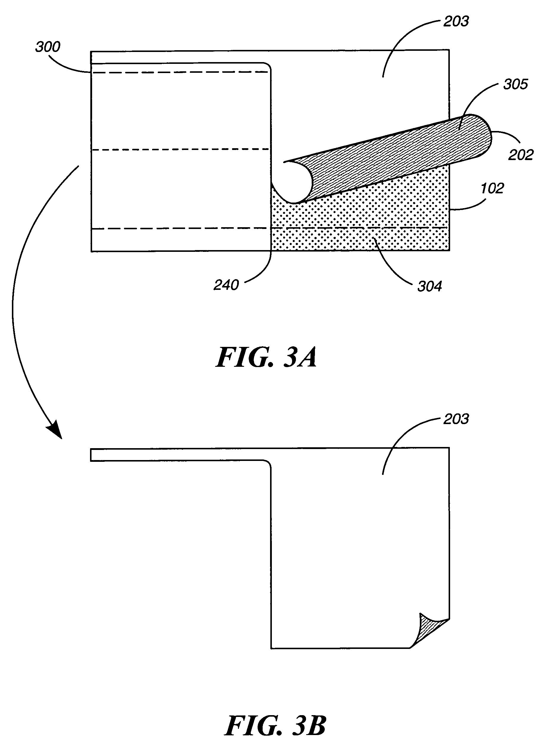
[0019]Another advantage of the present invention is that a self-mailer, including a document such as a certified mail form, is provided with an attached “Receipt for Certified Mail” (United States Postal Service Form 3800). This embodiment of the present invention allows for the printing of the inserted document and the receipt at the same time and in one printer pass. This results in a quick and easy generation of the self-mailer and associated receipt.
[0020]Another advantage of the present invention is that the present invention eliminates the possibility of a mismatch between a document and a Certified Mail card. Since both items are printed onto the same self-mailer, there is no need to seek matching documents and collate them together. Instead, both items are printed onto the same self-mailer and folded and sealed together to produce an item that is mailed.
[0021]Another advantage of the present invention is that the self-mailer is easily printable by a standard non-impact printer. Printing of the self-mailer does not require the adjustment of the printer. This is beneficial to the consumer as it results in a more efficient printing process.

Problems solved by technology

Self-mailers, however, do not come without their drawbacks.
One problem is producing the self-mailer.
Current folding / sealing machines are bulky and costly.
This is cost prohibitive for many businesses.
Another problem with the production of self-mailers is that current business form printing software requires duplex or multiple pass printers.
This is disadvantageous, as the current installed base of printers substantially comprises simplex or single pass printers.
However, with the increasing popularity of non-impact printers, especially among small business organizations, the percentage of organizations having the impact printers necessary to use such multi-part forms is decreasing.
However, by simply adapting the standard available technologies to produce forms that can be used with non-impact printers results in forms that do not have flexibility and the capability for efficient use with non-impact printers.
For example, impact self-mailers produced by machine-fold and seal technologies available in the 1980s and 1990s were often burdensome or clumsy to open.
At least two of these strips ran at right angles to the paper grain whereby perforations are least effective for providing a clean tear.
Such automatic folding machines are examples of equipment not available to many small business organizations.
Currently, there is no efficient solution to handle information where a notice, announcement or other information typically printed on an information postcard is sent via Certified Mail.
This is time consuming and prone to errors.

Method used


Image

  • Multi-label mailing form including certified self-mailer
  • Multi-label mailing form including certified self-mailer
  • Multi-label mailing form including certified self-mailer

Examples


first embodiment

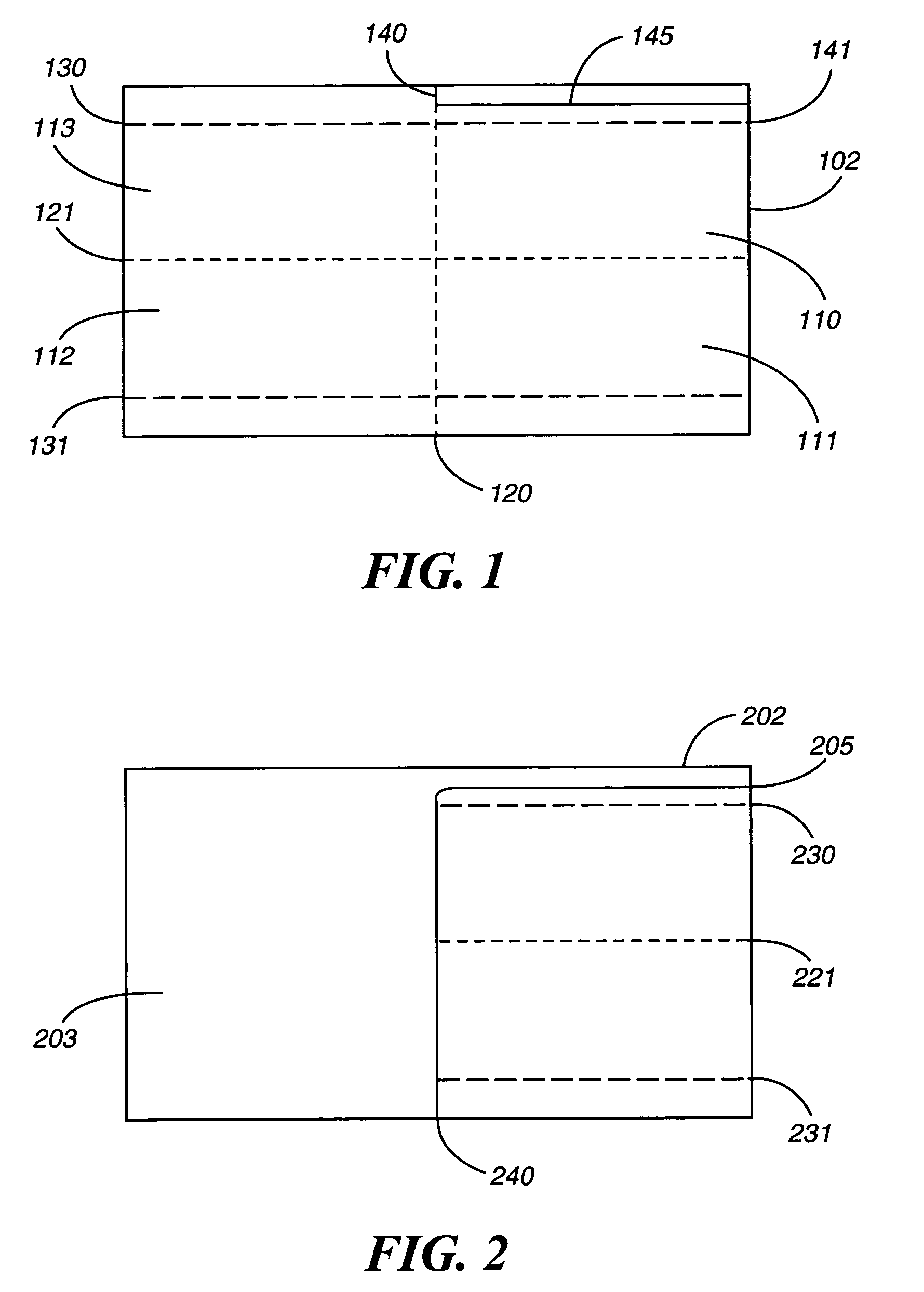
[0046]FIG. 1 shows the first side of a top ply 102 of the mailing form, or self-mailer, in one embodiment of the present invention. FIG. 1 shows that the top ply 102 is a rectangular sheet of paper having dimensions of a standard sheet of paper, e.g., 8.5×11 inches, 8.5×14 inches or A4. It is important to note, that other paper dimensions are possible to those skilled in the art, within the true scope and spirit of the present invention. The top ply 102 is composed of any number of paper materials and composites that are used as paper substitutes. The top ply 102 can receive printed information when passed through a simplex non-impact printer.

[0047]FIG. 1 shows that the top ply 102 includes a vertical fold line 120 that evenly divides the top ply 102 vertically in half. FIG. 1 also shows that the top ply 102 includes a horizontal fold line 121 that also evenly divides the top ply 102 in half, but horizontally. Thus, the first side of the top ply 102 is divided into four quadrants by...

second embodiment

[0070]FIG. 7 shows the first side of a top ply 702 of the mailing form, or self-mailer, in a second embodiment of the present invention. FIG. 7 shows that the top ply 702 is a rectangular sheet of paper having dimensions of 8.5×14 inches, for example.

[0071]FIG. 7 shows that the top ply 702 includes a vertical fold line 720 running vertically along the top ply 702. FIG. 7 also shows that the top ply 702 includes a horizontal fold line 721 running horizontally along the top ply 702. FIG. 7 further shows that the top ply 702 includes a perforation 722 running vertically near the right edge of the top ply 702. Additionally, FIG. 7 shows that the top ply 702 includes a perforation 730 running along the top edge of the top ply 702 from the left edge of the top ply 702 to the perforation 722 and a perforation 731 running along the bottom edge of the top ply 702 from the left edge of the top ply 702 to the perforation 722.

[0072]FIG. 7 further shows that the top ply 702 includes a die cut 74...

third embodiment

[0096]FIG. 17 shows another embodiment of the first side of a top ply 1702 of the mailing form, or self-mailer, in a third embodiment of the present invention. FIG. 17 is an alternative embodiment of the item depicted in FIG. 7. FIG. 17 shows that the top ply 1702 is a rectangular sheet of paper having dimensions of 8.5×14 inches, for example.

[0097]FIG. 17 shows that the top ply 1702 includes a vertical fold line 1720 running vertically along the top ply 1702. FIG. 17 also shows that the top ply 1702 includes a horizontal fold line 1721 running horizontally along the top ply 1702. FIG. 17 further shows that the top ply 1702 includes a perforation 1722 running vertically near the right edge of the top ply 702. Additionally, FIG. 17 shows that the top ply 1702 includes a perforation 1730 running along the top edge of the top ply 1702 from the left edge of the top ply 1702 to the perforation 1722 and a perforation 1731 running along the bottom edge of the top ply 1702 from the left edg...


PUM

PropertyMeasurementUnit
adhesiveaaaaaaaaaa
areaaaaaaaaaaa
forcesaaaaaaaaaa

Abstract

A mailing form for facilitating the mailing of a document is disclosed. The mailing form includes a bottom ply of the mailing form and an interspersed between the first side of the bottom ply (i.e. inner side of the bottom ply) and the second side of the top ply (i.e. inner side of top ply). The mailing form further includes a top ply of the mailing form and a removable portion of the top ply extending over the first side of the top ply. The mailing form further includes a vertical fold line for folding the mailing form after the top ply has been removed, and a horizontal strip of the first side of the bottom ply, the horizontal strip including adhesive that is exposed after the mailing form is folded. The mailing form further includes a horizontal fold line for folding the mailing form that has been folded along the vertical fold line.

Description

CROSS-REFERENCED APPLICATIONS[0001]This non-provisional application is a continuation-in-part of the non-provisional patent application Ser. No. 10 / 378,163 with inventor Warren Fabel entitled “MULTI-LABEL MAILING FORM FOR NON-IMPACT PRINTER” filed Feb. 28, 2003, now U.S. Pat. No. 6,945,565 which is hereby incorporated by reference in its entirety. This non-provisional application is also a continuation-in-part of the non-provisional patent application Ser. No. 10 / 255,375 with inventor Warren Fabel entitled “SINGLE SIDE IMAGED POSTAL FORM ASSEMBLY” filed Sep. 26, 2002, now abandoned which is hereby incorporated by reference in its entirety. Both of the aforementioned non-provisional applications are continuation-in-part applications of the non-provisional patent application Ser. No. 09 / 293,496 with inventor Fabel entitled “SINGLE-SIDE IMAGED POSTAL FORM ASSEMBLY” filed Apr. 15, 1999, now U.S. Pat. No. 6,717,938 which is hereby incorporated by reference in its entirety.PARTIAL WAIVER ...

Claims


Application Information

Patent Timeline
Patent Type & Authority Patents(United States)
IPC IPC(8): B42D15/00B23B9/00B65D27/00B42D15/02H04L12/14H04M3/42H04M3/53H04M3/56H04M7/00H04M15/00
CPCB42D15/02Y10T428/14Y10T428/1495B42P2241/22
Inventor FABEL, WARREN M.CORTEZ, JOSE B.AUCHTER, GLEN A.
Owner LASER SUBSTRATES
Learn More