Reflective encoder with three-dimensional code carrier

a technology of encoder and encoder, applied in the direction of converting sensor output, measurement device, instruments, etc., can solve the problem of image being out of focus

Inactive Publication Date: 2008-04-15
AVAGO TECH WIRELESS IP SINGAPORE PTE
View PDF4 Cites 89 Cited by
  • Summary
  • Abstract
  • Description
  • Claims
  • Application Information

AI Technical Summary

Problems solved by technology

Hence, if there is an error in the code strip to detector distance, the image will be out of focus and errors will result.
Unfortunately, transmissive recorders require that two separate components, the light source and the photodetector, be mounted and aligned with one another at the time of assembly of the encoder.

Method used


Image

  • Reflective encoder with three-dimensional code carrier
  • Reflective encoder with three-dimensional code carrier
  • Reflective encoder with three-dimensional code carrier

Examples


Embodiment Construction

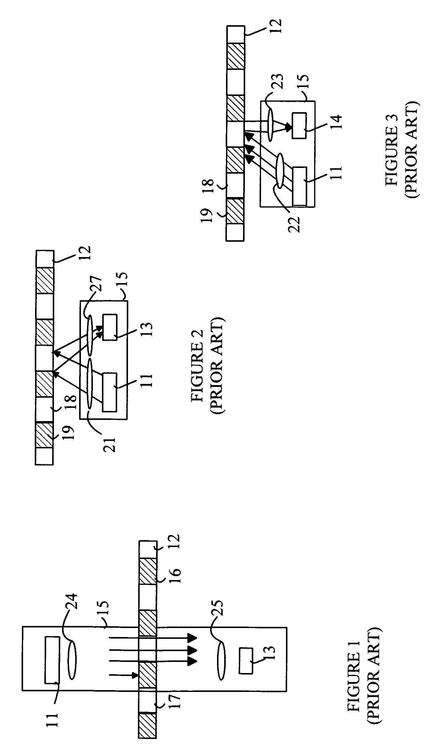
[0020]Refer now to FIGS. 1-3, which illustrate some typical encoder designs. The encoder can be divided into an emitter / detector module 15 and a code wheel or code strip. Module 15 includes an emitter 11 that illuminates a portion of the code strip 12. The illuminated code strip is viewed by detector 13. The emitter typically utilizes an LED as the light source. The detector is typically based on one or more photodiodes. FIG. 1 illustrates a transmissive encoder. In transmissive encoders, the light from the emitter is collimated into a parallel beam by a collimating optic such as lens 24. Code strip 12 includes opaque stripes 16 and transparent stripes 17. When code strip 12 moves between emitter 11 and detector 13, the light beam is interrupted by the opaque stripes on the code strip. The photodiodes in the detector receive flashes of light. The resultant signal is then used to generate a logic signal that transitions between logical one and logical zero.

[0021]The detector can incl...


PUM


Abstract

An encoder having a code pattern on a carrier and an emitter detector module is disclosed. The code pattern includes alternating reflective and opaque regions on a carrier that includes a planar surface. The emitter-detector module includes a light source that generates light and directs a portion of the generated light at the first side of the carrier and a first detector that detects light reflected from one of the reflective regions. The reflective regions include a three-dimensional element for directing light from the light source onto the first detector. The element has a surface that is inclined at an oblique angle with respect to the planar surface. The code pattern moves with respect to the emitter-detector module. The three-dimensional element can include a reflective imaging element that images the light source onto a surface of the first detector.

Description

BACKGROUND OF THE INVENTION[0001]Encoders provide a measurement of the position of a component in a system relative to some predetermined reference point. Encoders are typically used to provide a closed-loop feedback system to a motor or other actuator. For example, a shaft encoder outputs a digital signal that indicates the position of the rotating shaft relative to some known reference position that is not moving. A linear encoder measures the distance between the present position of a moveable carriage and a reference position that is fixed with respect to the moveable carriage as the moveable carriage moves along a predetermined path.[0002]Optical encoders utilize a light source and a photo detector to measure changes in the position of an encoding disk or strip. In a transmissive encoder, the encoding disk includes a series of alternating opaque and transparent stripes. The light source is located on one side of the code strip, and the photodetector is located on the other side...

Claims


Application Information

Patent Timeline
Patent Type & Authority Patents(United States)
IPC IPC(8): G01D5/34G01B11/14
CPCG01D5/34707G01D5/285
Inventor YEOH, THENG HOOITAN, HOCK AUNLUM, CHEE FOO
Owner AVAGO TECH WIRELESS IP SINGAPORE PTE
Why Eureka
Try Eureka