
Piezoelectric switch

a technology of piezoelectric switch and switch, which is applied in the field of electric switches, can solve the problems of compromising the success rate of the switch in use, and the drawback of the piezoelectric switch type described above, and achieves the effects of convenient use, low manufacturing cost, and optimized switch success ra

Inactive Publication Date: 2008-04-15
TOWER MFG
View PDF13 Cites 15 Cited by
  • Summary
  • Abstract
  • Description
  • Claims
  • Application Information

AI Technical Summary

Benefits of technology

"This patent describes a new and improved piezoelectric switch. The switch includes a piezoelectric element mounted within a protective housing, which is designed to optimize the success rate of the switch. The switch is easy to use, has a minimum number of parts, and is inexpensive to manufacture. The carrier that holds the piezoelectric element is designed to engage the housing to retain the carrier fixed in place within the interior cavity such that the piezoelectric element is coupled to the inner surface of the touch plate. The technical effects of this patent are improved functionality and reliability of the piezoelectric switch."

Problems solved by technology

Although well known and widely used in commerce, piezoelectric switches of the type as described above have been found to suffer from a notable drawback.
Specifically, it has been found that the use of double-sided tape to affix the piezoelectric element to the inner surface of the touch plate can compromise the success rate of the switch in use.
However, because the entire surface of the piezo crystal is evenly affixed to the inner surface of the contact plate by an adhesive (which may, in turn, weaken over time), the application of an input force onto the housing is just as likely to cause the outer periphery of the piezo crystal to deform as it is to cause the approximate center of the piezo crystal to deform, which is highly undesirable.

Method used


Image

  • Piezoelectric switch
  • Piezoelectric switch
  • Piezoelectric switch

Examples


Embodiment Construction

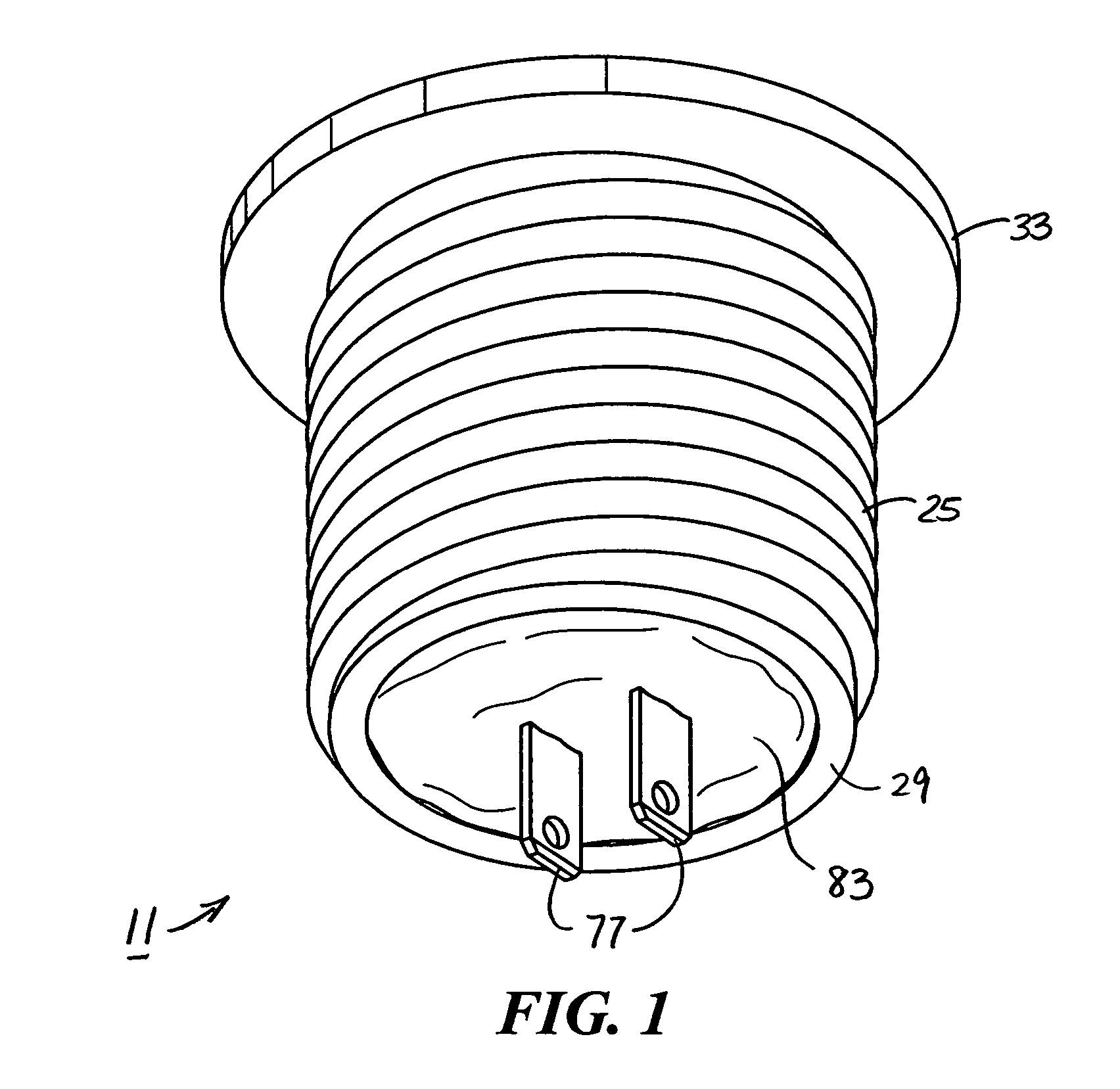
[0027]Referring now to FIG. 1, there is shown a piezoelectric switch that is constructed according to the teachings of the present invention, the piezoelectric switch being identified generally by reference numeral 11.

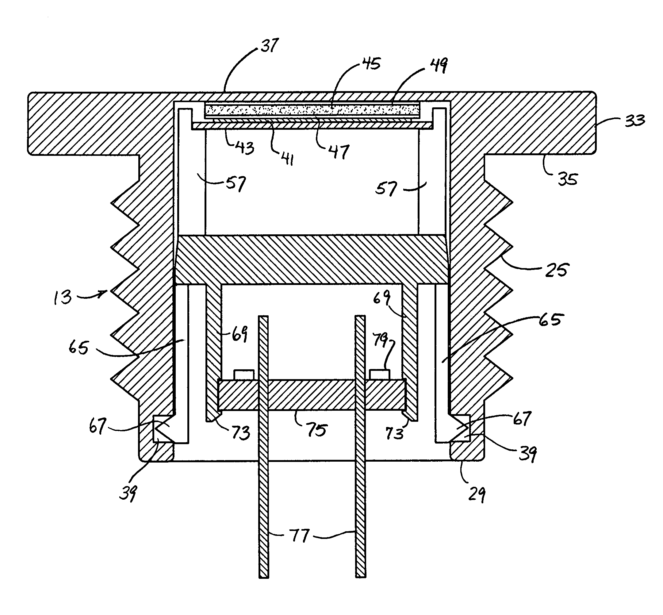
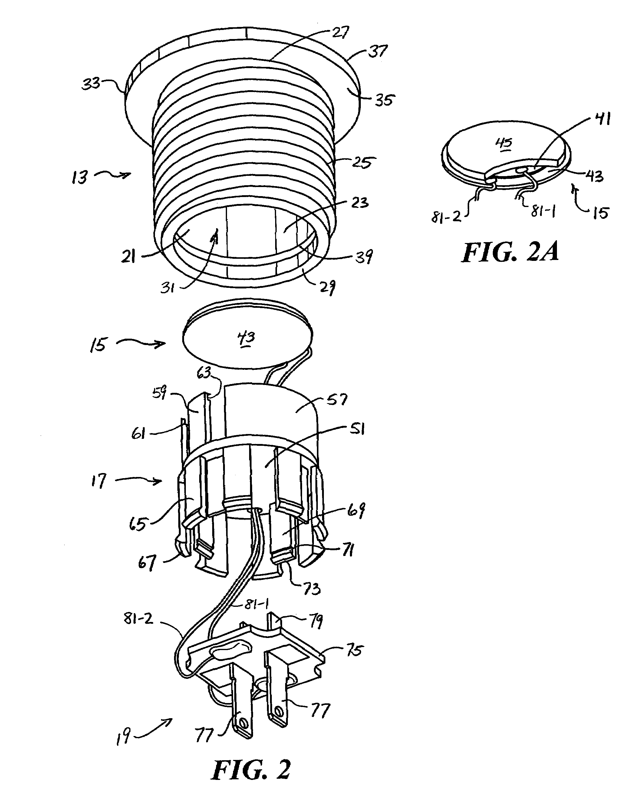
[0028]Referring now to FIG. 2, piezoelectric switch 11 comprises a housing 13, a piezoelectric element 15, a carrier 17 and a printed circuit board assembly 19.

[0029]Housing 13 is a unitary member that is preferably constructed out of a rigid and durable material, such as plastic or aluminum. Housing 13 comprises a cylindrical wall 21 which includes an inner surface 23, an outer surface 25, a first end 27 and a second end 29 which together define a partially-enclosed interior cavity 31 which is sized and shaped to receive the remaining components of piezoelectric switch 11, as will be described in detail below.

[0030]An enlarged disc-shaped touch plate, or button, 33 is integrally formed onto first end 27 of cylindrical wall 21, touch plate 33 comprising an inner surfac...


PUM


Abstract

A piezoelectric switch includes a piezoelectric element which is electrically connected to a printed circuit board by a pair of wires. A unitary plastic carrier is designed to retain both the piezoelectric element and the printed circuit board fixedly mounted thereon. In turn, the plastic carrier is sized and shaped to be co-axially disposed within the interior cavity of a generally cylindrically-shaped protective housing, wherein the plastic carrier is provided with at least one flexible finger which is configured to snap-fit into engagement within an annular groove formed in the inner surface of the housing so as to retain the carrier in place within the interior cavity. With the carrier fixed in place within the housing, an adhesive spacer disposes the piezoelectric element in contact with the inner surface of a touch plate provided in the housing. Accordingly, in use, the application of a tactile input onto the outer surface of the touch plate in turn causes the approximate center of the piezoelectric element to slightly deform. In response thereto, the piezoelectric element generates an output signal which passes to the printed circuit board. Based on the output signal received, the printed circuit board regulates the state of the piezoelectric switch.

Description

BACKGROUND OF THE INVENTION[0001]The present invention relates generally to electrical switches and more particularly to piezoelectric switches.[0002]Piezoelectric switches, also commonly referred to simply as piezo switches, are well known and widely used in the electrical switch industry.[0003]A piezoelectric switch traditionally includes a piezoelectric element comprising a disc-shaped piezoelectric plate and a disc-shaped conductive plate that are affixed together by an adhesive. The piezoelectric plate is commonly constructed out of piezo crystal and serves as the positive terminal for the switch. The conductive plate is typically constructed out of a conductive metal, such as brass, and serves as the negative terminal for the switch. Each of the above-described plates of the piezoelectric element is electrically connected to a printed circuit board which in turn supports the output prongs (i.e., conductive terminals) for the switch.[0004]The piezoelectric element and printed c...

Claims


Application Information

Patent Timeline
Patent Type & Authority Patents(United States)
IPC IPC(8): H01L41/08H10N30/00H10N30/88
CPCH03K17/964
Inventor AROMIN, VICTOR V.
Owner TOWER MFG
Learn More