Method and apparatus for transmitting and receiving power over optical fiber

a technology of optical fiber and transmission line, applied in the direction of electrical equipment, electromagnetic transmission, transmission, etc., can solve the problems of increasing installation cost, increasing operational cost, and not carrying electricity in the optical network

Inactive Publication Date: 2008-04-15
RPX CLEARINGHOUSE
View PDF14 Cites 130 Cited by
  • Summary
  • Abstract
  • Description
  • Claims
  • Application Information

AI Technical Summary

Benefits of technology

[0006]The present invention is directed to a method and apparatus for transmitting and receiving power over optical fiber. Power may be provided over an optical fiber system by providing an optical power converter to extract electrical power from the signals on the optical fiber. The power may be obtained from dedicated signals, from the data signal, or from a combination of signals. Optionally, the electrical power obtained from the optical signal may be combined with a source of local power. According to an embodiment of the invention, the optical signal includes a high frequency data portion that includes the data to be transmitted, and low frequency power signal portion. When the optical signal is received and converted into an electrical signal, the electrical signal will also include both a high frequency data signal and a low frequency power signal. The electrical signal is filtered to separate the data signal from the power signal, and the data signal is processed using known techniques. The power signal can be conditioned and / or regulated, if necessary, and provided either directly to a terminal piece of equipment, or may be combined with locally provided power to contribute at least a portion of the power required by the equipment. Optionally, the power may be stored in a local resident power supply, such as a battery, and charged by the optical power signal when the equipment is not in use.

Problems solved by technology

However, optical networks do not carry electricity, thus requiring optical components on the network to be powered by a local power source.
Establishing local power source connections increases installation costs and also increases operational costs.

Method used


Image

  • Method and apparatus for transmitting and receiving power over optical fiber
  • Method and apparatus for transmitting and receiving power over optical fiber
  • Method and apparatus for transmitting and receiving power over optical fiber

Examples


Embodiment Construction

[0014]The following detailed description sets forth numerous specific details to provide a thorough understanding of the invention. However, those skilled in the art will appreciate that the invention may be practiced without these specific details. In other instances, well-known methods, procedures, components, protocols, algorithms, and circuits have not been described in detail so as not to obscure the invention.

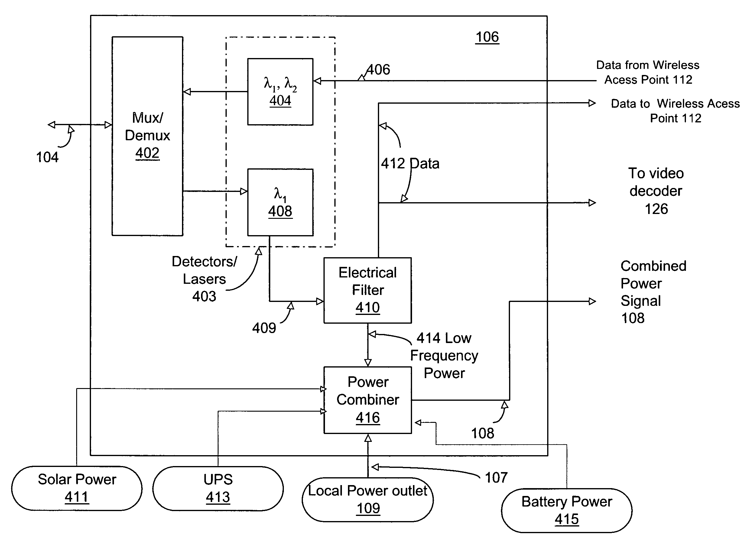
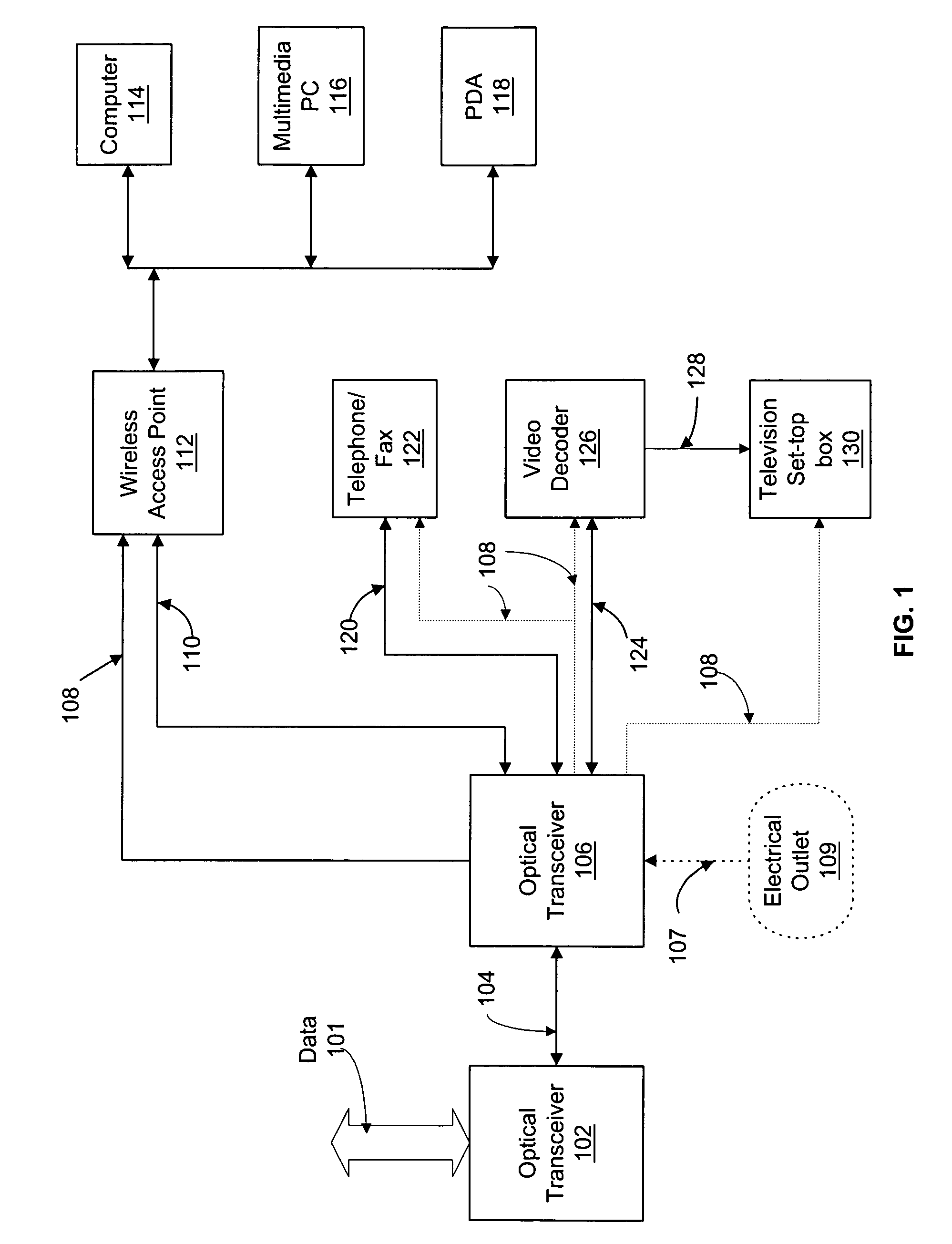
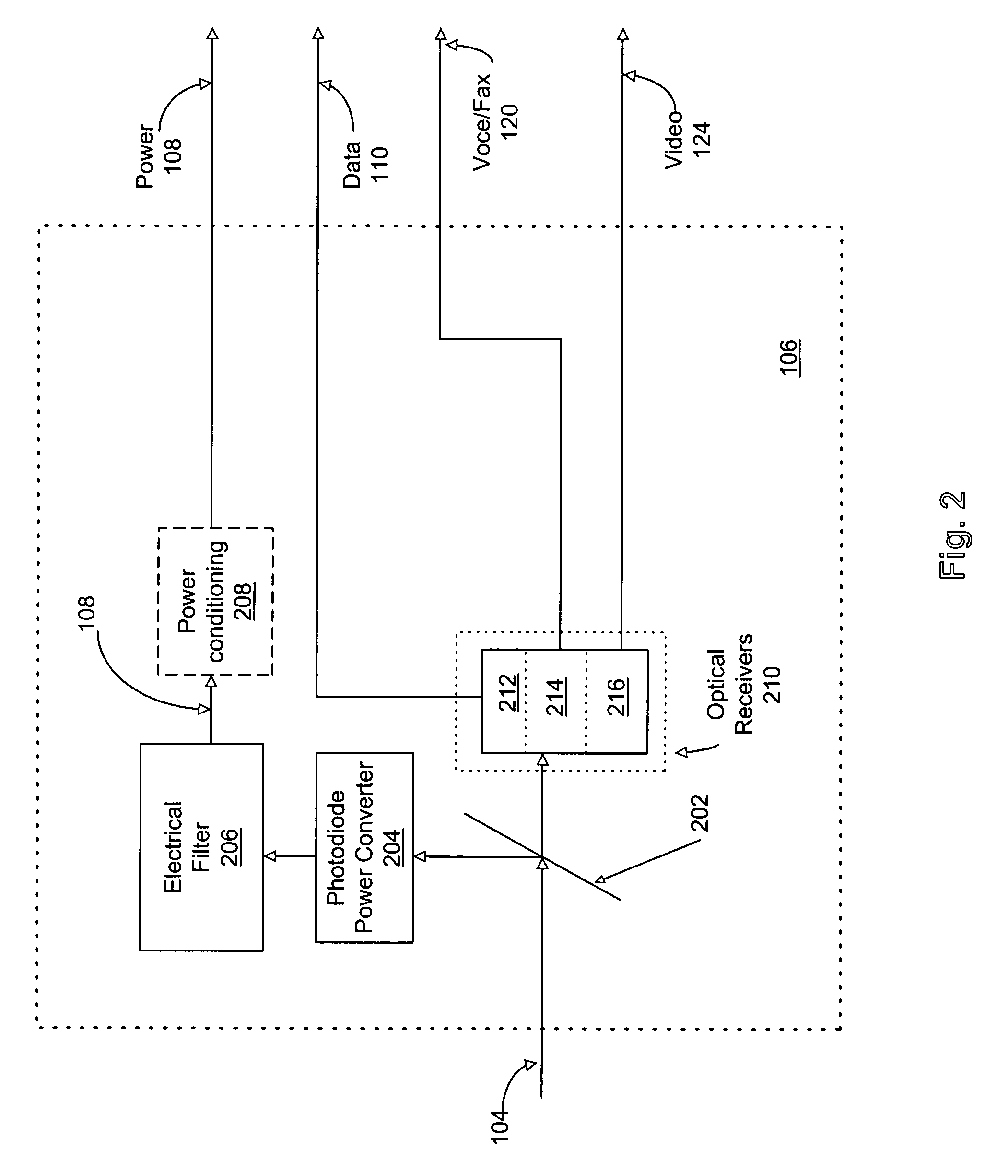
[0015]The present invention is directed toward transmitting and receiving power over optical fiber. Electrical power may be transmitted within an optical network via an optical fiber to provide total or partial power to one or more electrical devices on the optical network. Depending on the implementation of the embodiment of the invention, the optical signals may be dedicated power signals, combination power and data signals, data signals, and may be used to provided all the power for the device or may be used to provide partial power for the device. Optionally, where th...


PUM


Abstract

A method and apparatus for transmitting and receiving power over optical fiber is disclosed. In particular, a power over fiber system in which an optical network transmits electrical power via an optical signal and is also transmits data within the optical network as well. The optical signals include a high frequency data portion that includes the data to be transmitted, and either a constant or low frequency power signal portion. The optical signal is received and converted into an electrical signal by a photodetector/photodiode that is electrically filtered to separate the data signal from the power signal. The data signal is then processed using known techniques. The power signal can be conditioned and/or regulated, if necessary, and provided either directly to a terminal piece of equipment to provide all the required power thereto, or may be combined with locally provided power to contribute at least a portion of the power required by the equipment. The terminal piece of equipment may be a wireless access point.

Description

BACKGROUND OF THE INVENTION[0001]1. Field of the Invention[0002]The present invention relates generally to providing power in devices in a communication network and, in particular, to a method and apparatus for transmitting and receiving power over optical fiber.[0003]2. Description of the Related Art[0004]Optical fiber and copper wire are used extensively in the telecommunications area to transmit data. Of these two technologies, optical fiber is generally able to transmit larger quantities of data than copper wire, and is therefore being deployed to enable higher bandwidth communication services to be provided on existing networks. Additionally, optical fiber has other advantages, such as its ability to transport data without transporting electricity, which make it desirable in particular applications where transmission of electricity may be disadvantageous, such as where the channel may subject to a lightning strike.[0005]Optical networks, like other networks, may require regener...

Claims


Application Information

Patent Timeline
Patent Type & Authority Patents(United States)
IPC IPC(8): H04B10/00H04B1/16
CPCH02J17/00H04B10/807H02J50/30
Inventor FARIA, ROBERTOGOODWILL, DOMINIC J.
Owner RPX CLEARINGHOUSE
Why Eureka
Try Eureka