Premixing nozzle, combustor, and gas turbine
a technology of combustor and nozzle, which is applied in the field of gas turbines, can solve the problems of labor hour and shorten the life of the premixing nozzl
- Summary
- Abstract
- Description
- Claims
- Application Information
AI Technical Summary
Problems solved by technology
Method used
Image

Examples
first embodiment
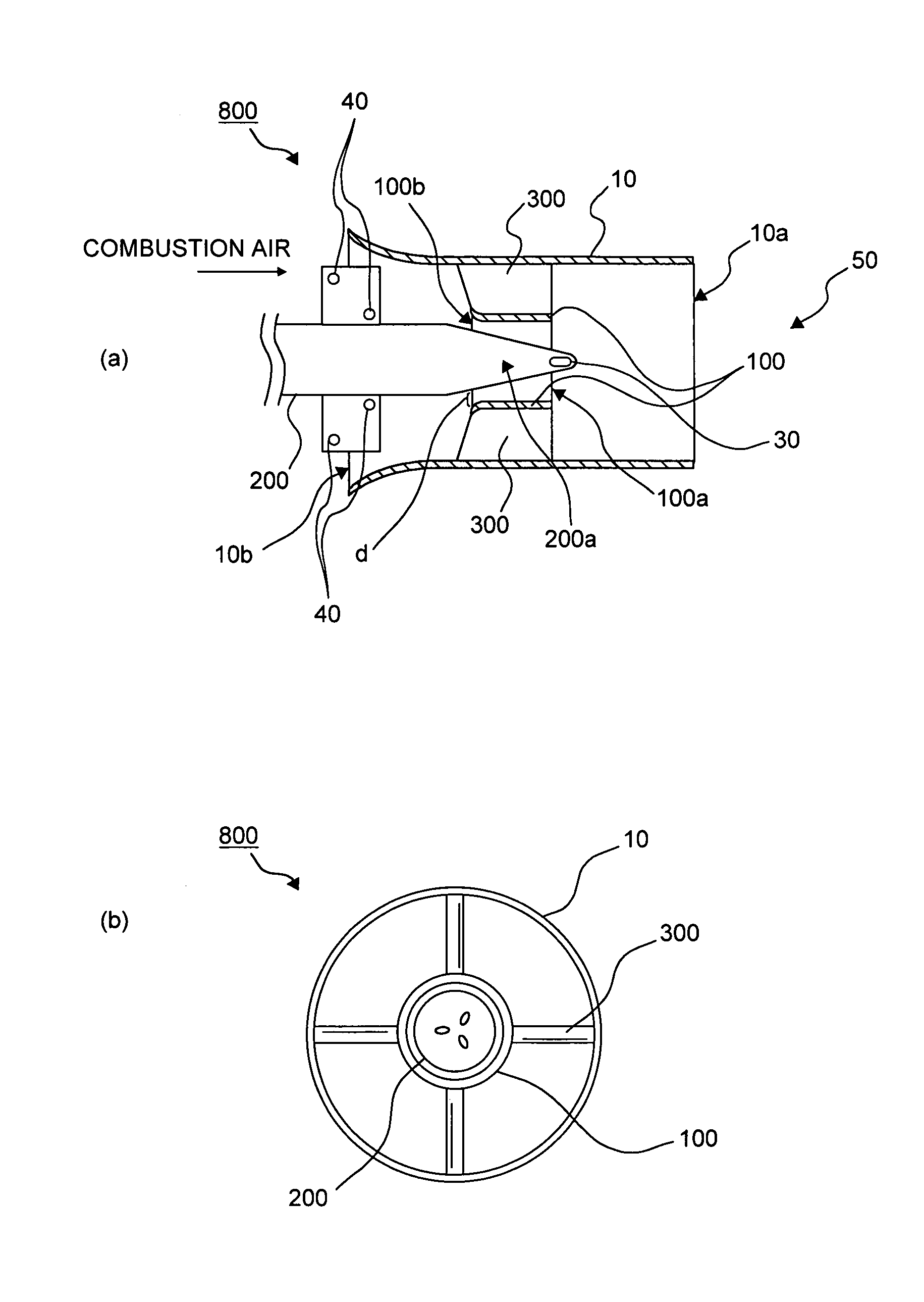
[0033]FIG. 1 shows a premixing nozzle of a gas turbine combustor according to this invention. This premixing nozzle has a feature in that a tip portion of a fuel nozzle shaft that is tapered toward a tip of the shaft is arranged in the inner periphery of a hub of a swirler, to allow the combustion air to flow into a gap between the tip of the fuel nozzle shaft and the inner peripheral surface of the hub of the swirler. The flow velocity near the center of a nozzle body is increased by the combustion air, to thereby bring the flow velocity distribution in the nozzle body close to a uniform state.
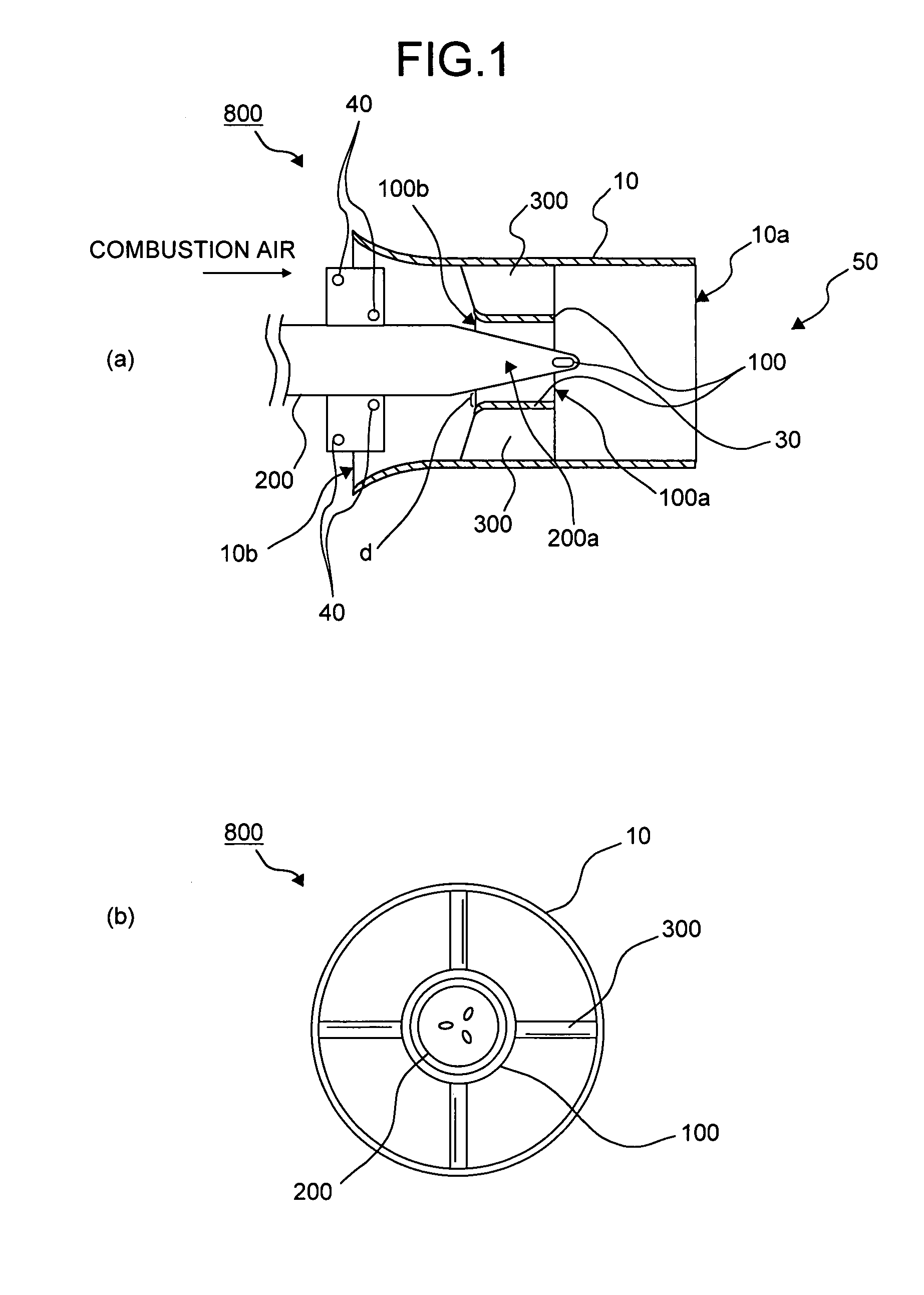
[0034]A premixing nozzle 800 according to the first embodiment includes a fuel nozzle shaft 200 of a system in which a liquid fuel such as light oil and heavy oil, and a gas fuel such as natural gas can be supplied to the combustion air as combustion gas. FIG. 2 shows a fuel nozzle shaft used in the premixing nozzle. As shown in FIG. 2(a), the fuel nozzle shaft 200 has a liquid fuel path 200d...
second embodiment
[0061]FIG. 7 is an axial cross section of a premixing nozzle according to the present invention. This premixing nozzle has a feature in that a tip of the fuel nozzle shaft is arranged in the upstream of the inlet of the hub. This premixing nozzle 806 is particularly suitable for a case in which the gas fuel is used singly. Therefore, an example in which the premixed gas is formed only by the gas fuel is explained first.
[0062]Swirler blades 306 are fitted inside the nozzle body 10, and the swirler blades 306 have a hub 106 at the central portion thereof. A fuel nozzle shaft 206 has a tip portion 206a having a diameter decreasing toward the flow direction, and the tip portion 206a is arranged in the upstream of an inlet 106b of the hub 106. A gas fuel is supplied from gas fuel supply holes 46 provided in gas fuel supply blades 26 to the combustion air fed from the compressor (not shown), to form a combustion gas.
[0063]A part of this combustion gas is swirled by the swirler blades 306 ...
fourth embodiment
[0071]FIG. 9 shows a premixing nozzle according to the present invention. This premixing nozzle has a feature in using a fuel nozzle shaft having a through hole for combustion gas axially penetrating the fuel nozzle shaft. This premixing nozzle 808 includes a fuel nozzle shaft 208 having a through hole for passing the combustion air as the combustion gas, to the downstream of swirler blades 310.
[0072]As shown in FIG. 9(b), the fuel nozzle shaft 208 is provided with an inner cylinder 150 axially penetrating the fuel nozzle shaft 208, as a through hole for the combustion air. An inlet 150b of this inner cylinder 150 is open in the upstream of the fuel nozzle shaft 208 (see FIG. 9(a)), and the shape of the inlet 150b is in a funnel shape so as to easily take in the combustion air, but the shape is not limited to the funnel shape.
[0073]An outlet 150a (FIG. 9(b)) of the inner cylinder 150 is open at a tip portion 208a of the fuel nozzle shaft 208, and the combustion air flowing into the ...
PUM
 Abstract
Description
Claims
Application Information
 - R&D
- Intellectual Property
- Life Sciences
- Materials
- Tech Scout
- Unparalleled Data Quality
- Higher Quality Content
- 60% Fewer Hallucinations
Browse by: Latest US Patents, China's latest patents, Technical Efficacy Thesaurus, Application Domain, Technology Topic, Popular Technical Reports.
© 2025 PatSnap. All rights reserved.Legal|Privacy policy|Modern Slavery Act Transparency Statement|Sitemap|About US| Contact US: help@patsnap.com