Apparatus and method for feed-forward image rejection in a dual conversion receiver

a dual-conversion receiver and image technology, applied in the direction of color television details, television system details, television systems, etc., can solve problems such as interference with down-conversion and reception

Inactive Publication Date: 2008-04-22
AVAGO TECH INT SALES PTE LTD
View PDF18 Cites 15 Cited by
  • Summary
  • Abstract
  • Description
  • Claims
  • Application Information

AI Technical Summary

Problems solved by technology

The image channel in a receiver is an unwanted channel that can interfere with the down-conversion and reception of a desired channel.

Method used


Image

  • Apparatus and method for feed-forward image rejection in a dual conversion receiver
  • Apparatus and method for feed-forward image rejection in a dual conversion receiver
  • Apparatus and method for feed-forward image rejection in a dual conversion receiver

Examples


second embodiment

[0046]FIG. 5B illustrates the feed forward image cancellation circuits 212a and 212b. This embodiment replaces the capacitors C1 and C2 in FIG. 5A with inductors L1 and L2. This embodiment may be necessary for a given SAW filter phase response to produce the desired image cancellation.

third embodiment

[0047]FIG. 5C illustrates the feed forward image cancellation circuits 212a and 212b. A single differential inductor L is employed instead of two shunted inductors. A similar embodiment may be employed with the shunted capacitors of FIG. 5A.

fourth embodiment

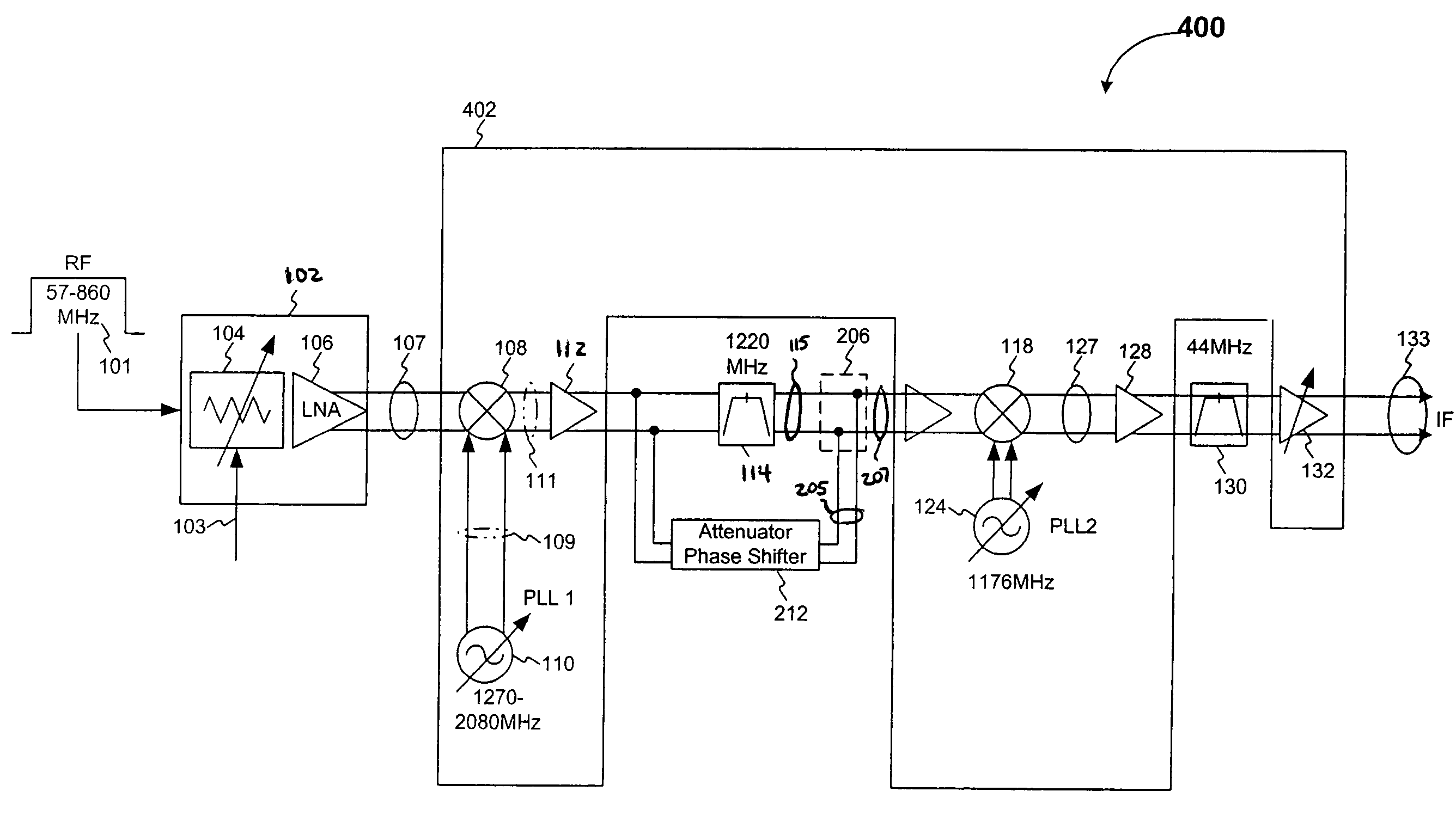
[0048]FIG. 6 illustrates the tuner 400 having the feed forward image cancellation circuits 212a and 212b. In FIG. 6, each image cancellation circuit 212 includes a first resistor R1, a second resistor R2, a capacitor C1, and an inductor L1. The capacitor C1 is between ground and a terminal that inter-connects the series resistors R1 and R2. This second-order circuit allows for more phase shift in the cancellation circuits. This might be required when the SAW phase shift is too small.

[0049]The component values for the image cancellation circuits 212a and 212b are selected so as to reduce the image frequency at 1132 MHz. However, those skilled in the arts will recognize that other component values could be selected based on the image frequency that is desired to be canceled. Furthermore, other component values could also be used based on the attenuation at the image frequency of the SAW filter 114. Still further, other network configurations could also be used to generate a signal tha...


PUM


Abstract

A receiver portion includes a bandpass filter (e.g. SAW filter) that performs channel selection from an input signal having a plurality of channels, and an image cancellation circuit that is in parallel with the bandpass filter. The bandpass filter performs channel selection to select a desired channel that falls in a passband of the bandpass filter. Since the passband is typically a few channels wide, the image channel falls outside the passband and is attenuated by the stopband attenuation of the bandpass filter. The image cancellation circuit includes an attenuator and a phase shifter. The attenuator is configured to have the same attenuation as the stopband attenuation of the bandpass filter at the image channel frequency, and phase shifter is configured to provide a phase shift of approximately 180 degrees. Therefore, the image cancellation circuit has an output that is equal in amplitude, but opposite in phase, to that of the bandpass filter at the image channel frequency. A summer combines the output of the image cancellation circuit with the bandpass filter output to further suppress the image channel frequency over that achieved by the bandpass filter alone.

Description

[0001]This application claims the benefit of U.S. Provisional Application No. 60 / 547,764, filed on Feb. 26, 2004, which is incorporated herein by reference.BACKGROUND OF THE INVENTION[0002]1. Field of the Invention[0003]The present invention generally relates to image rejection in a dual conversion receiver, and more specifically to improving image rejection using a feed-forward network that cancels the image frequency at the output of a channel selection filter.[0004]2. Background Art[0005]Television signals are transmitted at radio frequencies (RF) using terrestrial, cable, or satellite transmission schemes. Terrestrial and cable TV signals are typically transmitted at frequencies of approximately 57 to 860 MHZ, with 6 MHZ channel spacings in the United States and 8 MHz channel spacing in Europe. Satellite TV signals are typically transmitted at frequencies of approximately 980 to 2180 MHz.[0006]Regardless of the transmission scheme, a tuner is utilized to select and down-convert ...

Claims


Application Information

Patent Timeline
Patent Type & Authority Patents(United States)
IPC IPC(8): H04N5/50H03D7/18H04B1/10H04B1/12H04B1/18H04B1/26H04B1/28H04N5/44
CPCH04B1/123H04B1/28Y10S348/909
Inventor DAUPHINEE, LEONARDBURNS, LAWRENCE M.
Owner AVAGO TECH INT SALES PTE LTD
Why Eureka
Try Eureka